
Improved contact box for high-voltage switchgear

A high-voltage switchgear and contact box technology, applied in switchgear parts, switchgear guards/guards, guards/blinds that prevent contact with contacts, etc. It can increase the insulation distance, strengthen the insulation protection ability, and reduce the amount of partial discharge due to problems such as large amplification and switch cabinet safety hazards.

Active Publication Date: 2011-11-09
浙江省开化七一电力器材有限责任公司
View PDF0 Cites 0 Cited by
  • Summary
  • Abstract
  • Description
  • Claims
  • Application Information

AI Technical Summary

Problems solved by technology

[0003] 1. After the insulator receives the circuit breaker protruding from the opening, the contact arm of the circuit breaker is on the same side as the bolt that fixes the insulator. The insulation distance is small, and there is discharge phenomenon between the contact arm of the circuit breaker and the bolt, which may easily cause a breakdown accident of the circuit breaker
[0004] 2. After the busbar and the static contact are fixedly connected, because the busbar is too close to the top wall of the cylindrical body and the inner wall of the through groove, during operation, the electric field is very concentrated and it is easy to discharge on the top wall of the cylindrical body and the inner wall of the through groove , so as to accelerate the electrical aging of the insulator, which may easily cause breakdown and explosion of the insulator, and cause safety hazards in the switchgear
[0005] 3. Three contact boxes of the same size are fixed side by side on the panel of the high-voltage switch cabinet. There is a large gap between the mounting flanges, and the metal plate of the cabinet body is exposed in the gap, which may easily cause the contact arm of the circuit breaker to The discharge of the metal plate causes the breakdown accident of the circuit breaker
[0006] To sum up, the existing products have the defects of low insulation protection ability, many discharge parts and large partial discharge volume of the switchgear as a whole.

Method used


Image

  • Improved contact box for high-voltage switchgear
  • Improved contact box for high-voltage switchgear
  • Improved contact box for high-voltage switchgear

Examples


Embodiment Construction

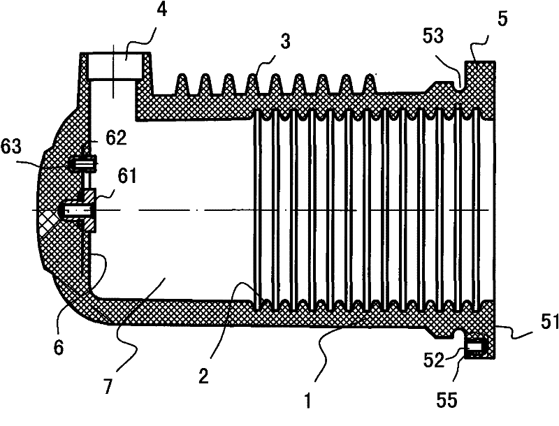
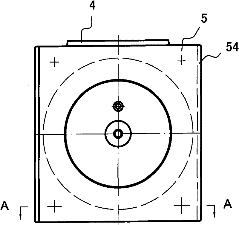
[0017] see figure 1 , and combined with figure 2 and image 3 . figure 1 The contact box in the box is placed horizontally, the right mounting flange 5 is square, and its edge has four fixed mounting screw holes 52, and the openings of the fixed mounting screw holes 52 are set on the inner plane 55 of the mounting flange 5, as The purpose of this change is to make the exposed part of the fastening bolt screwed on the fixed mounting screw hole 52 face away from the outer plane 51 of the mounting flange end, thereby increasing the creepage between the contact arm of the circuit breaker in the use state distance. The semicircular groove 53 on the cylindrical body 1 is mainly used to prevent the corona discharge phenomenon of the cabinet body to the cylindrical body 1 after installation, and the four fixing screw holes 52 accept metal fixing bolts to fix the contact box on the metal plate of the cabinet body On the other hand, semiconductor aprons or semiconductor paint can e...


PUM


Abstract

The invention discloses an improved contact box for a high-voltage switchgear, which comprises an insulator. The insulator of a mounting flange is formed by outward protrusion of the edge of an opening, and the mounting flange is provided with four fixed mounting screw holes. The closed ends of the screw holes are wrapped with an insulating layer. The rest of the insulator forms a cylinder. The top wall of an inner chamber of the cylinder is provided with a static contact mounting insert, and the position adjacent to the top wall is provided with a radial trough. The opening directions of thefour fixed mounting screw holes are positioned on an inner plane of the mounting flange, one end of the static contact mounting insert is 6 to 8 mm higher than the top wall plane, and the lapping edge of the mounting flange is provided with lapping steps. The external wall of the cylinder in transition to the inner plane of the mounting flange is provided with an annular semicircular groove, and the inside of the groove is provided with a semiconductor rubber ring or coated with semiconductor paint. The contact box has excellent insulation property, can effectively prevent a breaker from being stroke, and the insulator from being electrically aged quickly, and can prolong the service life of the insulator, thereby ensuring the safe and continuous operation of the high-voltage switchgear.

Description

【Technical field】 [0001] The invention belongs to an accessory used with electric equipment, in particular to an improved contact box for a high-voltage switch cabinet. 【Background technique】 [0002] The structure of the existing high-voltage switchgear contact box includes an insulator integrally formed by epoxy compound, with one end open and the other end closed. The edge of the opening protrudes to form a square mounting flange, and the rest forms a cylindrical body. . An inner skirt and an outer skirt are arranged on the inner and outer walls of the cylindrical body; the top wall of the inner cavity of the cylindrical body is provided with a static contact installation insert, and radially on the top wall of the cylindrical body. There is a through groove on the wall of the cylinder, which is used to receive the busbar, and the busbar radially extends into the inner cavity of the insulator through the through groove and is connected with the static contact. When inst...

Claims


Application Information

Patent Timeline
Patent Type & Authority Patents(China)
IPC IPC(8): H02B1/14H02B11/24
CPCH02B11/04
Inventor 余永松
Owner 浙江省开化七一电力器材有限责任公司
Learn More