Hot stuffy processing device for steel slag

A processing device and a hot and stuffy technology, applied in the field of steel-making slag recycling and processing devices, can solve the problems of prominent safety problems in the production process, increased pressure of the stuffy furnace, difficult maintenance, etc., and achieve stable and controllable product quality and improved production efficiency. , the effect of reducing maintenance costs

Active Publication Date: 2010-04-28
SHAOGUAN IRON & STEEL GROUP CORP GUANGDONG PROV
View PDF2 Cites 8 Cited by
  • Summary
  • Abstract
  • Description
  • Claims
  • Application Information

AI Technical Summary

Problems solved by technology

[0004] At present, hot steel slag hot stuffy equipment commonly used in China includes the device disclosed in Chinese patent document ZL200420058581.6. Above ℃, the installation frame and working lining of each section in the process of sub-spraying water cooling need to withstand sudden cooling and sudden heat. In addition, during the process of entering and unloading the slag, the excavator will mechanically collide with the hot stuffy equipment, which will easily cause bending deformation of the installation frame and deformation of the working lining. Breakage, resulting in frequent replacement of lining boards, etc., and difficult maintenance, high maintenance costs, and serious safety problems during the maintenance process; in addition, the gap between the working lining and the concrete pool wall is gradually emptied, the working lining is easily deformed and broken, and if it is not replaced in time, it will easily lead to high temperature. The state steel slag is in direct contact with the concrete pool wall, and under the action of high temperature, the concrete pool wall will burst and destroy the permanent layer structure, resulting in a short service life of the equipment
[0005] Another Chinese patent document ZL200720174489.X discloses a structure in which a layer of heat insulation is added in the gap between the working lining and the concrete pool wall. The working lining is fixed by a fixing component fixed on the concrete pool wall. After the fixed components and the working lining are deformed, it is very difficult to disassemble the working lining
If the working lining cannot be repaired in time, it will easily lead to direct contact between the high-temperature hot steel slag and the heat insulation layer and the concrete pool wall. Under the action of high temperature, the concrete pool wall will burst and the service life of the equipment will be short
[0006] According to the actual operation experience, it has been proved that the domestic common steel slag hot stuffy treatment device has accumulated 20 furnaces of hot stuffy steel slag in one month of normal use, and failures such as deformation of the installation frame, damage of the working lining, and fall-off of embedded parts occurred within one month, resulting in maintenance. Frequent, high maintenance costs, prominent safety problems in the production process, seriously affecting production efficiency, and extremely short equipment life
[0007] In addition, a breather valve is installed on the cover of the furnace to increase the pressure relief channel, but because the steam generated in the furnace contains a large amount of dust, it is easy to block the hole of the breather valve, and if it is not handled in time, the pressure in the furnace will increase suddenly and cause flying If it is serious, it may cause an explosion, seriously affecting production safety

Method used


Image

  • Hot stuffy processing device for steel slag
  • Hot stuffy processing device for steel slag
  • Hot stuffy processing device for steel slag

Examples


Embodiment Construction

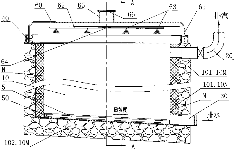
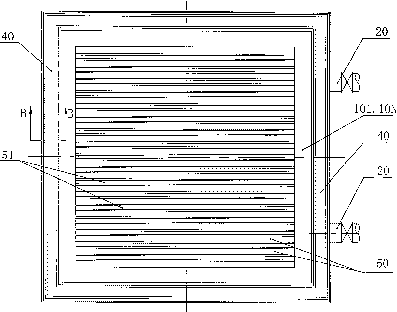
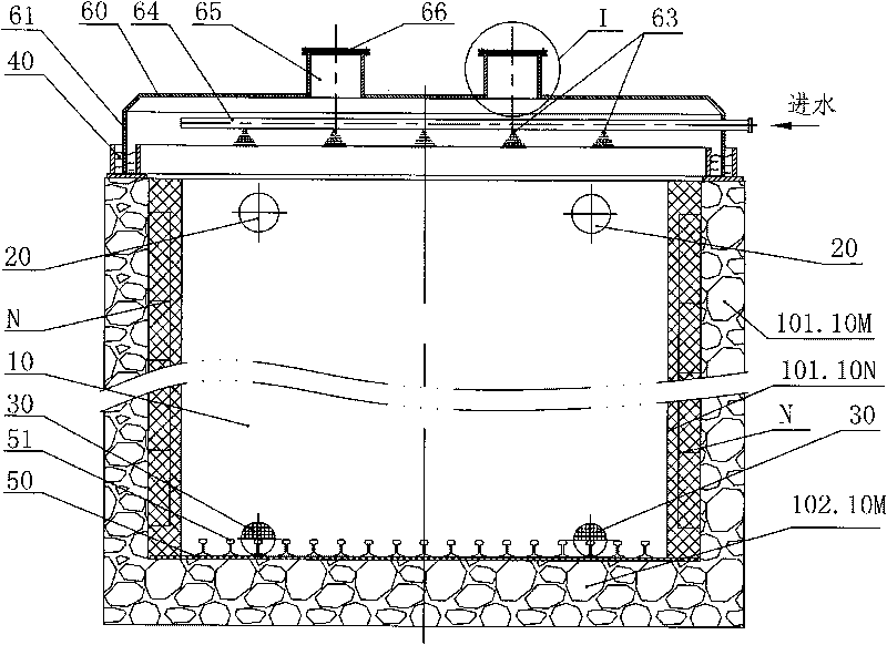
[0034] Such as Figure 1-8 , which are the main schematic diagram of the structure of the embodiment of the hot stuffy treatment device for steel slag of the present invention and the schematic diagrams from various angles of view, respectively. The upper end is open, the upper part of the tank wall 10 is provided with an exhaust pipe 20, the lower part of the tank wall 10 is provided with a drain pipe 30, and a circle of water seal grooves 40 with a U-shaped cross section is provided along the upper opening of the tank wall 10, and the tank wall 10 includes a primary The outer wall 10M of the heat-resistant concrete formed by pouring and tamping, the side 101 of the tank wall 10 also includes an inner wall 10N formed by one-time pouring and tamping of the steel fiber reinforced refractory castable; the outer wall 10M includes a steel mesh M (not shown ), embedded parts (not shown) are evenly distributed on the reinforced mesh M, and the inner wall 10N includes a reinforced me...


PUM

PropertyMeasurementUnit
lengthaaaaaaaaaa
densityaaaaaaaaaa
compressive strengthaaaaaaaaaa

Abstract

The invention relates to a hot stuffy processing device for steel slag, which comprises a tank wall, wherein the tank wall comprises a lateral surface, a bottom surface and an upper end opening; the upper part of the tank wall is provided with an exhaust pipe; the lower part of the tank wall is provided with an exhaust water pipe; a circle of water seal tank with a U-shaped cross section is arranged along the upper end opening of the tank wall, and the tank wall comprises an outer wall of heat-resisting concrete formed by pouring and tamping at one time; the lateral surface of the tank wall also comprises an inner wall formed by pouring and tamping a steel fiber reinforced fire-retarding pouring material at one time; the outer wall comprises a steel mesh M; pre-embedded parts are uniformly distributed and welded on the steel mesh M; the inner wall comprises a steel mesh N; the steel mesh N is in welding connection with exposed joints of the pre-embedded parts on the outer wall one by one; and the thickness of the outer wall is 1 to 2 times that of the inner wall. The hot stuffy processing device for the steel slag has higher hot stuffy processing efficiency, longer service life of equipment, lower maintenance cost, safer operation and simple structure.

Description

technical field [0001] The invention relates to an iron and steel smelting device, more specifically, the invention relates to a recycling and processing device for steel-making slag. Background technique [0002] Steel slag is an inevitable by-product of the steelmaking process, and its discharge accounts for about 15-20% of crude steel output. The utilization rate of steel slag in my country is still relatively low at present. In recent years, my country's iron and steel industry has developed rapidly. According to statistics, in 2008, my country's crude steel output reached 500 million tons, and the annual slag production reached 50-100 million tons. Reasonable utilization and effective recycling of steel slag is an important measure to achieve sustainable development of the steel industry, solve the shortage of steel scrap in steel enterprises, reduce production costs, and improve economic benefits of enterprises. It is also a favorable measure to protect the environment...

Claims


Application Information

Patent Timeline
Patent Type & Authority Applications(China)
IPC IPC(8): C21B3/10
Inventor 徐兰升谢传贤陈志光李铁军石建红林培芳罗元威
Owner SHAOGUAN IRON & STEEL GROUP CORP GUANGDONG PROV
Why Eureka
Try Eureka