Hydraulic power automation water treatment aeration cycle system

A circulation system and water treatment technology, applied in water/sewage multi-stage treatment, light water/sewage treatment, oxidized water/sewage treatment, etc., can solve the problem of slow filter filtration speed, no use of sterilization equipment, and increased maintenance workload and other problems, to achieve the effect of reducing maintenance workload, eliminating corrosion phenomenon, and less post-maintenance workload

Inactive Publication Date: 2010-05-12
郑州浪鲸泳池设备制造有限公司
View PDF0 Cites 3 Cited by
  • Summary
  • Abstract
  • Description
  • Claims
  • Application Information

AI Technical Summary

Problems solved by technology

This kind of water treatment system has the following defects: 1. Ordinary filters have slow filtration speed, poor filtration accuracy, large floor space, large abrasion during work, and heavy maintenance workload in the later stage
2. There is no equipment for adding oxygen to the water, so it is not suitable for the occasions of circulating water treatment such as landscape water bodies
3. The drug dissolving device needs power to add the drug into the water, which increases energy consumption
4. No independent sterilization equipment is used, and the sterilization effect is limited only by dosing sterilization
5. Many components such as water pumps and filters contain metal components, which will cause corrosion if they are in contact with water for a long time, thus affecting water quality
6. The hair of tourists often falls into the landscape water body. The existing water treatment system does not add a decontamination device for hair. After long-term use, the hair will enter the various components of the system and remain in the narrow parts of each component (or pipeline). Over time, it is easy to cause waterway blockage, which increases the maintenance workload in the later period

Method used


Image

  • Hydraulic power automation water treatment aeration cycle system
  • Hydraulic power automation water treatment aeration cycle system

Examples


Embodiment Construction

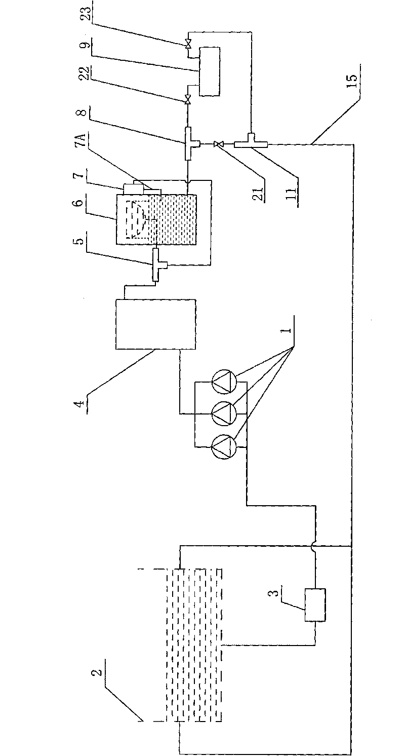
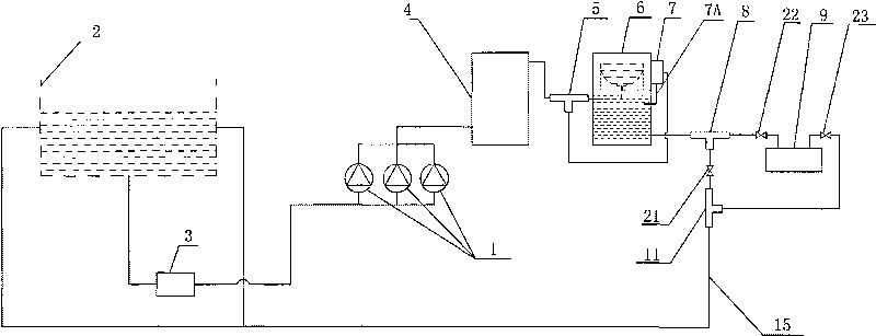
[0012] Such as figure 1 As shown, the hydraulic automatic water treatment aeration circulation system of the present invention includes a water pump group 1 connected to one side of the water storage tank 2, and a filter net decontamination device 3 is arranged in series between the water pump group 1 and the water storage tank 2, and the water pump group 1 The water outlet of the water outlet is connected with a high-speed composite filter material filter 4 through a pipeline, and the water outlet of the high-speed composite filter material filter 4 is connected with the water inlet of a drug-dissolving device tee 5, and an outlet of the drug-dissolving device tee 5 The water outlet is connected with an aeration box 6 through a pipeline, and the other water outlet of the drug dissolver tee 5 is connected with a gravity type drug dissolver 7 through a pipeline, and the gravity type drug dissolver 7 is fixedly connected to the aeration box 6 And its outlet 7A is connected with ...


PUM


Abstract

The invention discloses a hydraulic power automation water treatment aeration cycle system, comprising a water pump communicated with one side of a reservoir; the water outlet of the water pump is successively communicated with a high-speed composite filter material filter, an aeration tank, a gravity-type drug dissolving device and a sterilizer inlet tee joint via a pipeline, wherein one outlet of the sterilizer inlet tee joint is communicated and provided with a water return pipeline, and the other outlet of the sterilizer inlet tee joint is communicated and provided with a photocatalyst biocide device of which the outlet is communicated and provided with a sterilizer outlet tee joint; the sterilizer outlet tee joint is connected on the water return pipeline in series by other two ports; the water return pipeline between the sterilizer inlet tee joint and the sterilizer outlet tee joint is provided with a valve; the valve is respectively connected in series between the photocatalyst biocide device and the sterilizer inlet tee joint as well as between the photocatalyst biocide device and the sterilizer outlet tee joint; and the water return pipeline is communicated with the reservoir. The invention has simple structure, small floor area, high degree of automation and small later-stage maintenance workload and is suitable for circulating water treatment of water works, swimming pools, bathing beaches, lakes, waterscape, ornamental fish ponds and the like.

Description

technical field [0001] The invention relates to a water treatment system. Background technique [0002] The water treatment system is used to purify water quality. The existing water treatment system includes a water pump connected to the water source, and a filter is connected to the outlet of the water pump. The source water is purified in the filter, and then dosing into the water. One or more of bactericides, deoxidizers, scale inhibitors, flotation agents, coagulation aids, and of course other water treatment chemicals can also be added. Finally, the treated source water is returned to the water source or supplied to the water use unit. This water treatment system has the following defects: 1. Common filters have slow filtration speed, poor filtration accuracy, large floor space, large abrasion during work, and heavy post-maintenance workload. 2. There is no equipment for adding oxygen to the water, so it is not suitable for the occasions of circulating water treatmen...

Claims


Application Information

Patent Timeline
Patent Type & Authority Applications(China)
IPC IPC(8): C02F9/08C02F1/74C02F1/30
Inventor 黄江峰
Owner 郑州浪鲸泳池设备制造有限公司
Why Eureka
Try Eureka