
Delayed coagulation well cementation method of high-pressure gas underground gas storage wells

A technology for delaying solidification and gas storage wells, which is applied in shaft equipment, earthwork drilling, wellbore lining, etc. It can solve problems such as aging gas storage wells, difficult cleaning, accidents, etc., to ensure the quality of cementing, ensure safety performance, and ensure The effect of tightness

Inactive Publication Date: 2010-05-12
徐英 +3
View PDF0 Cites 6 Cited by
  • Summary
  • Abstract
  • Description
  • Claims
  • Application Information

AI Technical Summary

Problems solved by technology

[0005] 1. The bundled hose belt is left in the ground, and the bonding between the hose belt and the cement slurry is not firm, which affects the cementing quality; 2. When the cement slurry is pumped, the hose belt will expand and bulge. Expansion will cause the lateral displacement of the gas storage well device, which will make the outer ring space of the outer wall of the gas storage well device and the wellbore wall uneven. The imported cement slurry is uneven, and even some positions are not injected with cement slurry, which also causes the gas storage well device to be fixed in the wellbore not firmly, and the cementing quality is poor
3. What is more serious is that during the sinking process of the gas storage well device, the hose belt is easy to rub and wear on the wellbore wall, which will cause the hose belt to break and open, and the cement slurry will flow from the This rupture and the opening flow out instead of the bottom nozzle of the hose belt, so that the drilling fluid in the outer ring space below the rupture cannot be discharged, so that these parts cannot be filled with cement slurry, and the gas storage well device is solidified. Poor quality of well fixation brings serious safety hazards and even makes it unusable
[0007] 1. The residual cement on the sealing surface of the bottom opening of the gas storage well device and the sealing surface of the plugging head is difficult to clean, which affects the sealing quality of the gas storage well; at the same time, the cleaning water easily enters the annulus at the bottom of the well and mixes with the cement slurry to form too thin Mixed slurry affects the cementing quality and corrodes the gas storage well device
[0008] 2. After grouting, the plugging head of the plugging device and the opening at the bottom of the gas storage well device are sealed and sealed by operating the drill pipe. Due to the uneven deformation of the drill pipe length, its alignment is difficult and the tightening operation is difficult. The seal is easily damaged, and the sealing torque cannot be controlled to affect the sealing quality
[0009] 3. The rubber sealing ring on the plugging head is easy to age after the gas storage well is used, causing the gas storage well to leak, and the gas storage well is scrapped because it cannot be repaired at the bottom of the well
[0010] Both of the above two cementing methods will lead to poor cementing quality, poor sealing, and gas leakage of the gas storage well device, which will make the gas storage well scrapped or have a low service life. of security incidents

Method used


Image

  • Delayed coagulation well cementation method of high-pressure gas underground gas storage wells
  • Delayed coagulation well cementation method of high-pressure gas underground gas storage wells
  • Delayed coagulation well cementation method of high-pressure gas underground gas storage wells

Examples


specific Embodiment approach

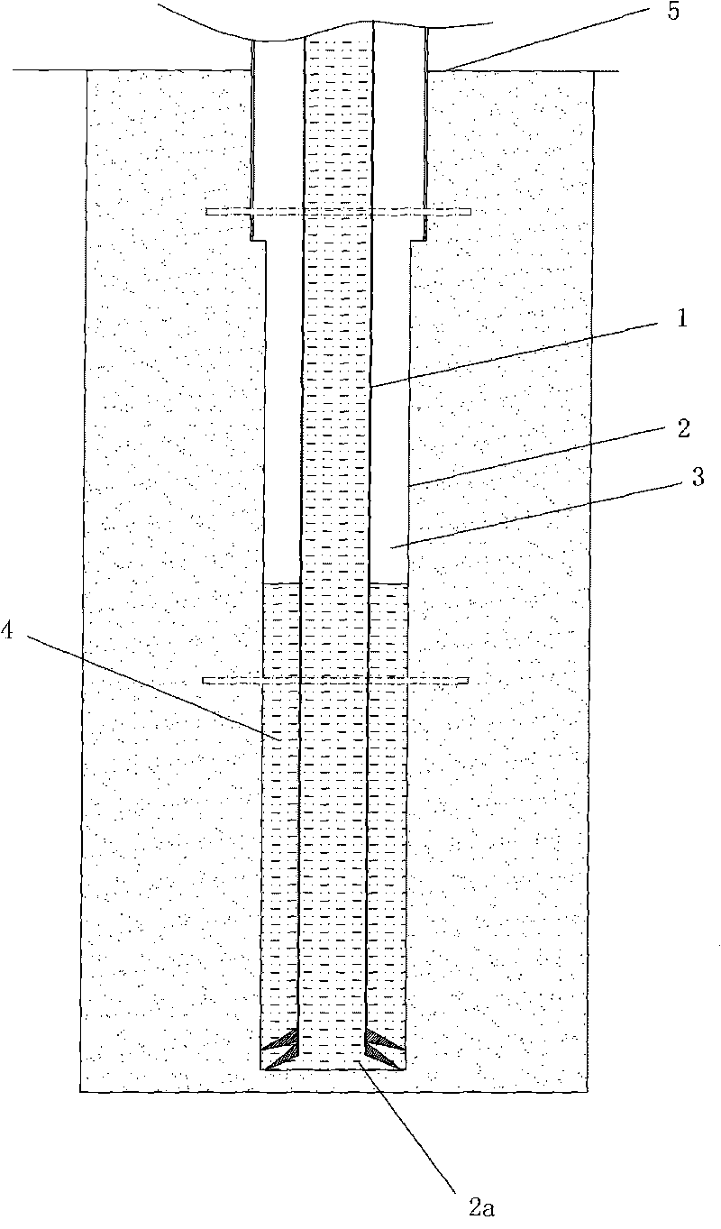
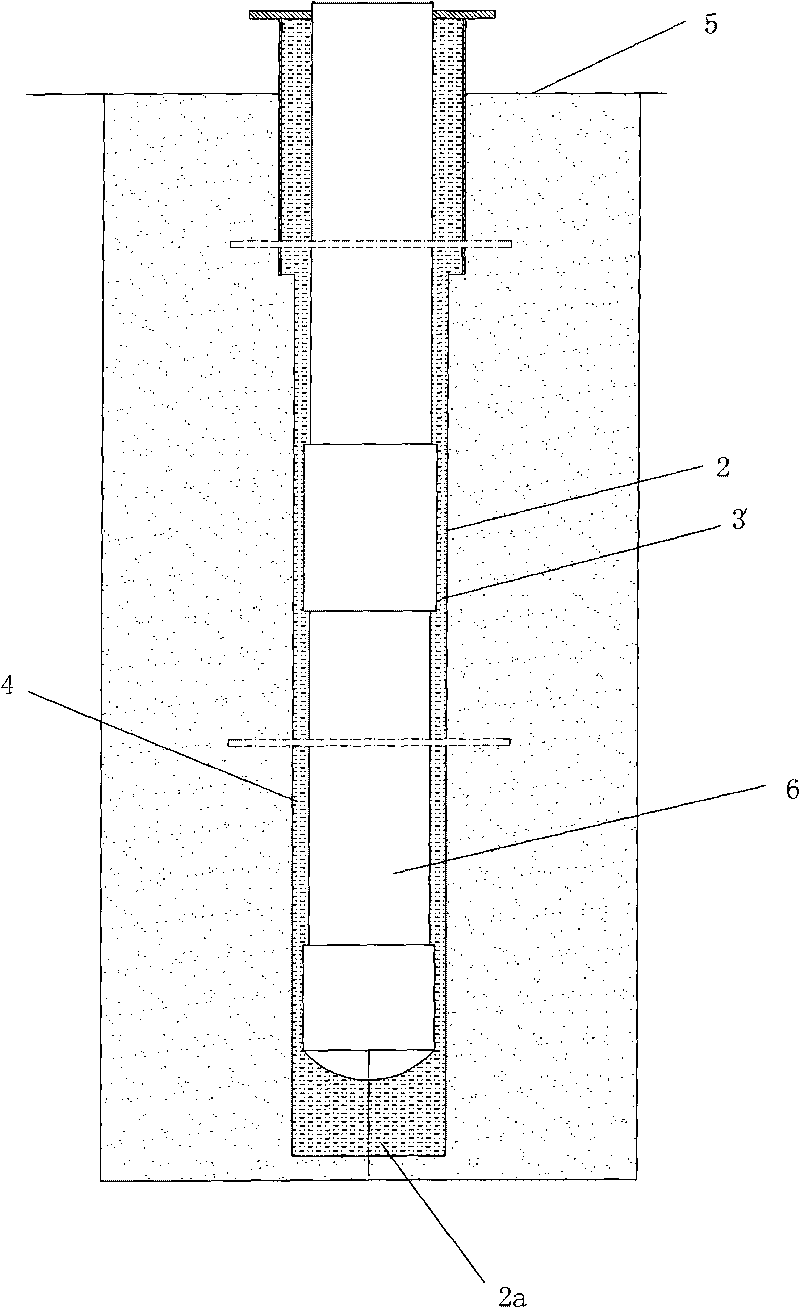
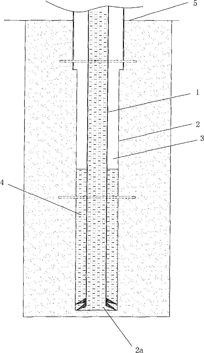
[0028] figure 1 and figure 2 Shown, a kind of embodiment of the present invention is: the delayed solidification cementing well method of high-pressure gas underground gas storage well, and its concrete steps are:

[0029] A, Drilling: Drill out the shaft 2 of the gas storage well with the drill bit at the front end of the drilling rod 1;

[0030] B. Grouting Connect the upper port of the inner cavity of the drill pipe 1 to the mud pump, and through the mud pump and the inner cavity of the drill pipe 1 to the bottom 2a of the wellbore and the annular space 3 between the outer wall of the drill pipe 1 and the wall of the wellbore 2, from Slowly inject the retarded cement slurry 4 from bottom to top until the retarded cement slurry 4 fills the annular space 3 and overflows the ground 5;

[0031] C. Installation of the well storage device Pull out the drill pipe 1, sink the cylindrical gas storage well device 6 with a diameter larger than the drill pipe into the well shaft 2 f...


PUM


Abstract

The invention relates to a delayed coagulation well cementation method of high-pressure gas underground gas storage wells, comprising the following steps of: A. drilling well; B. grouting: grouting retarding cement slurry to the bottom of a well cylinder and an annular space between the outer wall of a drill stem and the wall of the well cylinder through an inner cavity of the drill stem from down to top until the retarding cement slurry overflows the ground; C. installing a storage well device: lifting the drill stem, sinking the gas storage well device to the well cylinder filled with retarding cement slurry to a set position of the well cylinder, and completing filling of the cement slurry; D. and testing pressure: carrying out pressure test on the gas storage well device for 4 hours; lifting the gas storage well device and repeating the operations from step A to step D when pressure test is not qualified; and completing well cementation when the pressure test is qualified. The well cementation method has good well cementation quality, the combination of the gas storage well device and the wall of the well cylinder is firm, and the gas storage well has good sealing performance, high security and strong reliability, thereby the possibility of accidents of air leak, and the like is greatly reduced.

Description

technical field [0001] The invention relates to a delayed solidification cementing method in the construction process of a high-pressure gas storage well. Background technique [0002] As an alternative energy to petroleum, natural gas is both environmentally friendly and economical. It is developing rapidly in my country and has a wide range of uses. Compared with other gas storage devices, high-pressure underground gas storage wells for storing compressed natural gas have many advantages such as high safety and low risk, and are widely used in CNG (compressed natural gas) vehicle filling stations, urban natural gas peak-shaving stations and other places; Since it was included in the national standard specification in 2010, it has developed rapidly across the country. In gas filling stations and peak shaving stations, high-pressure gas underground gas storage wells have basically replaced gas cylinders and gas storage tanks. [0003] Cementing is a key procedure that affec...

Claims


Application Information

Patent Timeline
Patent Type & Authority Applications(China)
IPC IPC(8): E21D5/04
Inventor 徐英邓小川李湘蜀熊标
Owner 徐英
Learn More