Self-coupling cold source heat pump circulating device of low-temperature exhaust heat power generating system in low temperature exhaust steam condensation process

A low-temperature waste heat and power generation system technology, which is applied to steam engine devices, machines/engines, mechanical equipment, etc., can solve problems such as cold source loss, low efficiency, and low thermal cycle efficiency, and achieve reduced cold source loss and power consumption , The effect of improving the thermal cycle efficiency

Active Publication Date: 2010-05-12
NORTH CHINA UNIVERSITY OF SCIENCE AND TECHNOLOGY +1
View PDF0 Cites 21 Cited by
  • Summary
  • Abstract
  • Description
  • Claims
  • Application Information

AI Technical Summary

Problems solved by technology

Therefore, the latent heat of vaporization released by the condensation of exhaust steam is released into the ambient atmosphere through the cooling water, forming the heat sink loss in the Rankine cycle
[0004] As we all know, the purpose of the thermal cycle of the working medium for power generation is to convert the waste heat into electric energy. The biggest problem of the known low-temperature waste heat power generation system is that the thermal cycle efficiency is very low, generally between 22% and 25%, and the ineffe

Method used


Image

  • Self-coupling cold source heat pump circulating device of low-temperature exhaust heat power generating system in low temperature exhaust steam condensation process
  • Self-coupling cold source heat pump circulating device of low-temperature exhaust heat power generating system in low temperature exhaust steam condensation process

Examples


Embodiment Construction

[0011] The present invention will be described in detail below in conjunction with the accompanying drawings and embodiments.

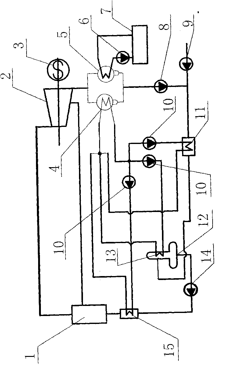
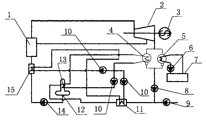
[0012] A self-coupling cold source heat pump circulation device in the exhaust steam condensation process of low-temperature waste heat power generation system, such as figure 1 As shown, compared with the known low-temperature waste heat power generation thermodynamic cycle system, the special point of the present invention is to use the self-coupling cold source heat pump cycle system of the exhaust steam condensation process to recycle the latent heat of vaporization released by the condensation of exhaust steam. In the figure, waste heat Boiler 1, steam turbine 2, generator 3, water-cooled condenser 5, circulating water pump 6, cooling tower 7, condensate water pump 8, make-up water pump 9, deaerator 12, and feed water pump 14 constitute a known low-temperature waste heat power generation thermodynamic cycle The heat pump condenser 4, the heat pum...


PUM


Abstract

The invention relates to the technical field of low-temperature exhaust heat power generation at low temperature, in particular to a self-coupling cold source heat pump circulating device of a low-temperature exhaust heat power generating system in the low temperature exhaust steam condensation process. The self-coupling cold source heat pump circulating device comprises a conventional low-temperature exhaust heat power generating heat circulation system, a heat pump type condenser which is arranged parallel with a water-cooled condenser is arranged at an exhaust steam outlet of a lower pressure cylinder of a steam turbine; a gaseous state working medium outlet of the heat pump type condenser is divided into three paths which respectively pass through a heat pump system compressor, wherein a first path passes through a heat pump condensed water heater, a second path passes through a heat pump deoxidized heater and a third path passes through a heat pump water feeding heater and then returns to a liquid state working medium input of the heat pump type condenser; the heat pump water feeding heater is arranged between a condensing water pump and a deaerator; the heat pump deoxidized heater is arranged on the deaerator; and the heat pump water feeding heater is arranged at a water feeding inlet of a water feeding pump and an exhaust heat boiler. The invention substantially improves the exhaust heat utilization efficiency of the low-temperature exhaust heat power generating system and enables the system to produce more power energy under the condition that exhaust heat sources are the same.

Description

Technical field: [0001] The invention relates to a device for improving the thermal cycle efficiency of low-temperature waste heat power generation, in particular to a self-coupling cold source heat pump cycle device for low-temperature waste heat power generation system exhaust steam condensation process for the purpose of reducing cold source loss and improving thermal cycle efficiency. Background technique: [0002] At present, the known low-temperature waste heat power generation thermodynamic cycle device adopts the Rankine cycle method, and its process is described as: the working medium absorbs the low-temperature waste heat of the flue gas in the waste heat boiler and raises the temperature at a constant pressure to form two low-pressure and high-pressure systems with different working capabilities. Steam; high-pressure steam enters the main steam port of the steam turbine to perform constant entropy work, and converts the heat energy carried by the steam into the mec...

Claims


Application Information

Patent Timeline
IPC IPC(8): F01K27/02F01K11/02
Inventor 王子兵张玉柱胡长庆王春波王宏利张闯
Owner NORTH CHINA UNIVERSITY OF SCIENCE AND TECHNOLOGY
Why Eureka
Try Eureka