Anti-clogging clay pipe packing subsurface flow constructed wetland

An artificial wetland and anti-clogging technology, applied in chemical instruments and methods, water/sludge/sewage treatment, biological water/sewage treatment, etc., can solve problems such as limited sewage treatment capacity, easy breeding of mosquitoes, and decline in wetland functions , to achieve efficient sewage treatment capacity, improve sewage treatment efficiency, and large specific surface area

Active Publication Date: 2010-05-19
SHANDONG UNIV
View PDF0 Cites 10 Cited by
  • Summary
  • Abstract
  • Description
  • Claims
  • Application Information

AI Technical Summary

Problems solved by technology

However, the surface flow has the disadvantages of large area, easy breeding of mosquitoes, low efficiency, and the treatment effect is greatly affected by the climate.
Subsurface flow constructed wetlands are generally favored by environmental protection technology workers because of their low investment, low energy consumption, high efficiency, small footprint,

Method used


Image

  • Anti-clogging clay pipe packing subsurface flow constructed wetland
  • Anti-clogging clay pipe packing subsurface flow constructed wetland
  • Anti-clogging clay pipe packing subsurface flow constructed wetland

Examples


Embodiment 1

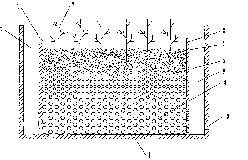
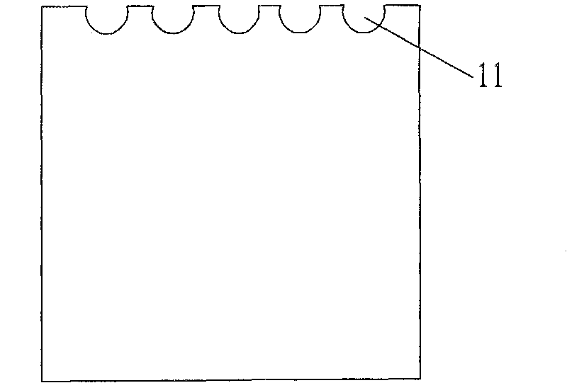
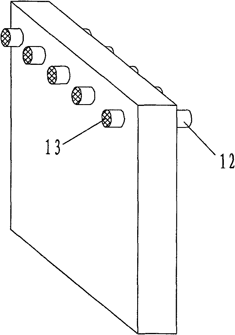
[0017] Such as figure 1 As shown, the present invention mainly includes a wetland main body 1, a water storage tank 2, a water distribution plate 3, a large pottery pipe packing layer 4, a small pottery pipe packing layer 5, a soil packing layer 6, wetland plants 7, a water retaining plate 8 and a water storage pool9. The wetland main body 1 is made of cement and bricks, and the bottom is treated with anti-seepage to prevent sewage from penetrating and polluting groundwater. The inner left side of wetland main body 1 (with figure 1 Shown position judgment) is provided with water distributing plate 3, and the right side is provided with water retaining plate 8. The space between the left side wall of the wetland main body 1 and the water distribution plate 3 forms a water storage tank 2 , and the space between the right side wall and the water retaining plate 8 forms a water storage tank 9 . The structure of the water distribution board 3 is as figure 2 , The top is provid...

Embodiment 2

[0020] This embodiment is basically the same as Embodiment 1 in terms of wetland composition, the difference being the filler layer. The filler layer in this embodiment is also divided into three layers. The bottom filler is a large pottery pipe with a thickness of 50 cm, and the middle layer is laid with vermiculite with a thickness of 30 cm; the upper layer The filler is pastoral soil with a thickness of 20cm.

Embodiment 3

[0022] This embodiment is basically the same as Embodiment 1 in terms of wetland composition, the difference being the packing layer. The packing layer in this embodiment is also divided into three layers. The bottom packing is a large pottery pipe with a thickness of 50 cm, and the middle packing is gravel with a thickness of 20 cm; the upper layer The filler is pastoral soil with a thickness of 30cm.


PUM

PropertyMeasurementUnit
Thicknessaaaaaaaaaa
Lengthaaaaaaaaaa
Thicknessaaaaaaaaaa

Abstract

The invention provides an anti-clogging clay pipe packing subsurface flow constructed wetland comprising a wetland main body, a water distribution plate, a water storage tank, a multi-dimension packing layer, a water baffle and an impounding reservoir; the outer layer of the wetland main body is of a brick masonry structure, and the inner wall and the bottom are of impermeable layer structures; the water distribution plate is arranged at one side in the wetland main body, and the water storage tank is formed in a space between the wall surface at the side and the water distribution plate; the water baffle is arranged at the other side in the wetland main body, and the impounding reservoir is formed in a space between the wall surface at the side and the water baffle, and the bottom of the impounding reservoir is provided with a water outlet; the multi-dimension packing layer is arranged in a space between the water distribution plate and the water baffle and is divided into an upper layer, a middle layer and a lower layer, the packing at the lower layer is a clay pipe with larger external diameter, the packing at the middle layer is a clay pipe, a gravel or a roseite with small external diameter, the packing at the upper layer is natural soil or the combination of upper natural soil and lower turf, and plants growing in wetlands are planted in the packing at the upper layer. The invention improves the processing efficiency to the greater extent, prevents clogging and can provide larger special surface area and increase the biomass.

Description

technical field [0001] The invention relates to an anti-clogging pottery pipe filler underflow artificial wetland, which belongs to the technical field of sewage purification. Background technique [0002] Constructed wetlands are divided into surface flow constructed wetlands and subsurface flow constructed wetlands. However, the surface flow has disadvantages such as a large area, easy breeding of mosquitoes, low efficiency, and a large impact on the treatment effect by the climate. Subsurface flow constructed wetlands are generally favored by environmental protection technology workers because of their low investment, low energy consumption, high efficiency, small footprint, good thermal insulation, and ease of operation. However, traditional methods mostly use stones and gravels as Filling, the subsurface flow rate is low, when the particle load is high, the insoluble matter is deposited, and it is easy to block, making the water flow unsmooth, the function of the wetla...

Claims


Application Information

Patent Timeline
IPC IPC(8): C02F3/32C02F3/34
CPCY02W10/10
Inventor 张建李超娜张成禄李晔赵星辰梁博张鹤峤
Owner SHANDONG UNIV
Why Eureka
Try Eureka