Optical driving micro valve and driving method thereof

A light-driven, micro-valve technology, applied in sliding valves, valve details, diaphragm valves, etc., can solve the problems of high power consumption, high electric field voltage, and long response time, and achieve simple manufacturing steps, large transmission power, and simple structure Effect

Inactive Publication Date: 2010-05-19
FUDAN UNIV
View PDF0 Cites 31 Cited by
  • Summary
  • Abstract
  • Description
  • Claims
  • Application Information

AI Technical Summary

Problems solved by technology

Although the piezoelectric valve has the characteristics of high sensitivity and fast response, it requires high electric field voltage, high energy consumption and high risk, so it is difficult to be directly applied
Electrostatically driven microvalve has fast response time and low power, but the driving force is small
Although the thermal drive method has a simple structure, it consumes a lot of power and takes a long time to respond
In addition, traditional electrical, magnetic and thermal power supplies make the miniaturization of the structure a big problem due to the need for wires and some conversion devices

Method used


Image

  • Optical driving micro valve and driving method thereof
  • Optical driving micro valve and driving method thereof
  • Optical driving micro valve and driving method thereof

Examples


Embodiment Construction

[0024] Specific embodiments of the present invention will be described in detail below. It should be noted that the embodiments described here are for illustration only, and are not intended to limit the present invention.

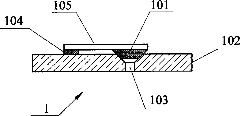
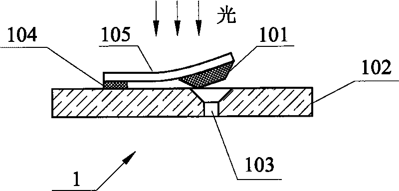
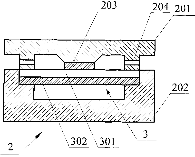
[0025] The light-driven microvalve in the present invention includes at least one deformable unit, and the unit includes a photodeformable material that is stretched and deformed under light. As shown in the figure, the microvalve has two structures, one is a cantilever beam structure 1 and the other is a valve membrane structure 2 .

[0026] The light-driven microvalve 1 with a cantilever beam structure is composed of a cantilever bracket 104 , a valve plug 101 and a cantilever beam 105 made of photodeformable material. One end of the cantilever beam 105 is fixedly connected to the cantilever bracket 104 by an adhesive, the other end is bonded to the valve plug 101 , and the rest is suspended in the air. The mating surface of the valve plug 101 and the ...


PUM


Abstract

The invention belongs to the technical fields of materials and micro machinery, in particular relating to an optical driving micro valve and a driving method thereof. The optical driving micro valve comprises a unit capable of generating deformation, and the unit comprises a photoinduced deformation material capable of generating telescopic deformation under the condition of illumination. The micro valve can be in a cantilever beam structure or valve membrane structure, wherein the cantilever beam structure comprises a substrate, a cantilever support, a valve plug and a cantilever beam made of the photoinduced deformation material; and the valve membrane structure comprises a valve base and a substrate, the space between the base and the substrate forms a flow channel of the micro valve, and an upper valve membrane positioned on the valve base is jointed with a lower valve membrane positioned on the substrate. The invention also provides a method of driving the micro valve, which comprises the following steps: irradiating the light onto the photoinduced deformation material of the micro valve, and then, controlling the opening and the closing of the micro valve through the deformation of the photoinduced deformation material. The micro valve of the invention has simple structure and smaller size and is suitable for the technical fields of micro fluid transmission and control and micro machinery. The optical driving method of the invention has the advantages of large transmission power, non-contact, rapidness, accuracy, cleanness and the like and realizes the purpose of directly converting the optical energy into the mechanical energy.

Description

technical field [0001] The invention belongs to the technical field of materials and micromachines, and in particular relates to a microvalve directly driven by light and a method for driving the microvalve. Background technique [0002] With the continuous development of micromechanical system (MEMS) research, the requirements for actuators are getting higher and higher: direct drive, large driving force, large displacement, fast response, etc. The development of photodeformable materials and their composite materials with excellent performance, and the development of microvalves directly driven by light energy are of great significance to microfluidic control systems. With the increasing application of microfluidic system technology, including bioengineering, drug delivery, chemical analysis, military, medical care, space exploration, etc., and with the development of human genetic engineering, the role of microfluidic systems in life sciences has become increasingly promi...

Claims


Application Information

Patent Timeline
Patent Type & Authority Applications(China)
IPC IPC(8): F16K3/22F16K7/14F16K31/00
Inventor 俞燕蕾朱玉田李晓英章园园陈茂林黄海涛邢星刘恒
Owner FUDAN UNIV
Why Eureka
Try Eureka