Laser resonant cavity automatic cavity adjusting system and method based on interference fringe picture skeleton line processing

A laser resonant cavity and interference fringe technology, applied in the field of lasers, to overcome the complex structure, improve speed and repeatability, and eliminate subjective errors.

Inactive Publication Date: 2011-04-06
NAT UNIV OF DEFENSE TECH
View PDF0 Cites 0 Cited by
  • Summary
  • Abstract
  • Description
  • Claims
  • Application Information

AI Technical Summary

Problems solved by technology

[0007] The technical problem to be solved by the present invention is to combine manual cavity tuning with automatic cavity tuning to overcome the deficiencies of the existing automatic cavity tuning technology, and use digital image processing technology to extract the output collimated beam of the laser resonator after the manual cavity tuning is completed Based on the interference fringe skeleton line, a resonant cavity collimation evaluation function is established, and the iterative control algorithm is used to control the cavity mirror movement so that the evaluation function approaches the extreme value, thereby realizing high-precision automatic collimation of the resonant cavity

Method used


Image

  • Laser resonant cavity automatic cavity adjusting system and method based on interference fringe picture skeleton line processing
  • Laser resonant cavity automatic cavity adjusting system and method based on interference fringe picture skeleton line processing
  • Laser resonant cavity automatic cavity adjusting system and method based on interference fringe picture skeleton line processing

Examples


Embodiment Construction

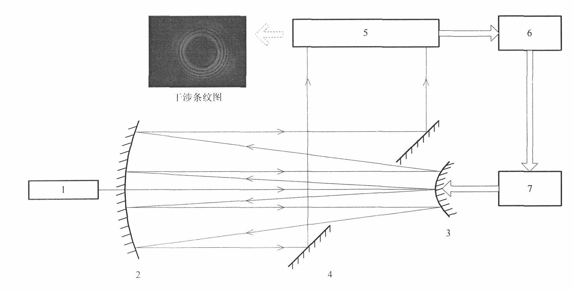
[0044] The laser resonator has various structure types, and the present embodiment is as follows figure 1 The concave-convex cavity structure shown is an example. The concave mirror 2 and the convex mirror 3 constitute a laser resonator, and the distance between them meets the cavity length requirement of the resonator. The convex mirror 3 is installed on a five-dimensional (front and back, left and right, up and down, pitch, yaw) adjustable electric mirror frame and is driven by a control circuit. The adjustable electric mirror frame and the control circuit together constitute the cavity mirror control system 7 . The concave mirror 2 remains stationary. The outcoupling mirror 4 is mounted on a mechanically adjustable optical support, placed at an angle of 45 degrees to the axis of the resonator, and has a rectangular or oval large hole in the center; the outcoupling mirror is placed close to the convex mirror; the guiding laser 1 is made of He -Ne laser, placed behind the c...


PUM


Abstract

The invention discloses laser resonant cavity automatic cavity adjusting system and method based on interference fringe picture skeleton line processing. The automatic cavity adjusting system comprises a guide light laser, a laser resonant cavity, a coupling output mirror, a camera, a computer and a cavity mirror control system, wherein the laser resonant cavity comprises an adjustable cavity mirror. The invention also provides an automatic cavity adjusting method corresponding to the automatic cavity adjusting system, which can perform rapid and precise judgment on the alignment of the laserresonant cavity and provide a control signal in real time for the cavity mirror control system, thereby achieving the aim of rapidly and automatically adjusting a cavity. By adopting the cavity adjusting system and the cavity adjusting method, the precision, speed and repeatability of the traditional manual cavity adjusting method can be effectively improved. In addition, the method can be further popularized and applied to the automatic adjustment of an optical system with an interference fringe of an output light field.

Description

technical field [0001] The invention relates to the fields of laser technology and the like, and further refers to a laser resonant cavity automatic tuning system and method based on the skeleton line processing of interference fringe patterns. Background technique [0002] The quality and output power of the laser output beam have a lot to do with whether the laser resonator is collimated. The misadjustment of the cavity mirror will lead to the decrease of the laser beam quality and laser power, and even produce extremely uneven intensity distribution. Therefore, before the laser works, the collimation adjustment of the resonator is one of the important prerequisites to ensure that the laser outputs high-power and high-quality beams. [0003] At present, the cavity tuning methods of laser resonators are mainly divided into two directions: manual cavity tuning and automatic collimation. [0004] In terms of artificial cavity adjustment, the currently widely used method is ...

Claims


Application Information

Patent Timeline
Patent Type & Authority Patents(China)
IPC IPC(8): H01S3/086G05B15/00
Inventor 伏思华毛宏军龙学军胡永军胡浩军谢文科
Owner NAT UNIV OF DEFENSE TECH
Why Eureka
Try Eureka