

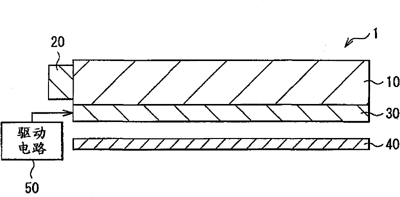
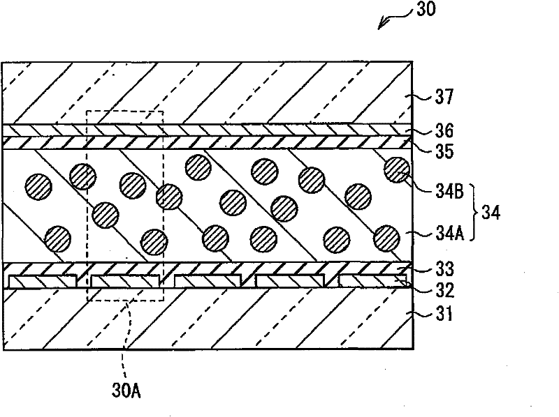
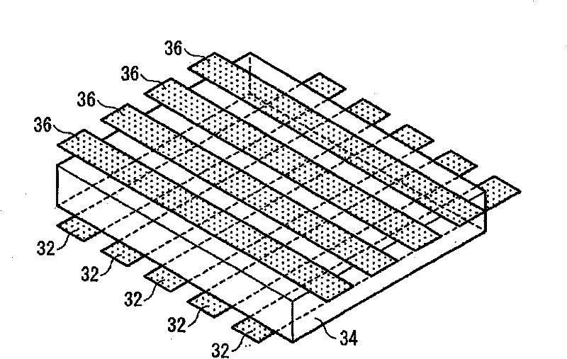
Illuminating device, display device, and method of manufacturing light modulation element
A technology for light modulation elements and lighting equipment, applied in lighting and heating equipment, optical elements, light guides of lighting systems, etc., can solve problems such as difficulty in implementing partial modulation of light sources, and achieve light leakage elimination, high transparency, and improved display brightness. Effect
- Summary
- Abstract
- Description
- Claims
- Application Information
AI Technical Summary
Problems solved by technology
Method used
Image

Examples
example
[0097] Examples of the present invention will be described below. Note that the examples are illustrative, and the present invention is not limited to these examples.
[0098] [Unit formation method]
[0099] An electrode pattern having a width of 10 mm was formed by a laser ablation method on an ITO-coated glass substrate (125 mm×125 mm). The resultant was subjected to ultrasonic application cleaning with an alkaline detergent, rinsed with ultrapure water, and dried by air blowing to form an electrode pattern substrate. Then, a vertical alignment film made of a polyimide-based material was coated on the electrode pattern substrate by a spin coater, and baked at 200° C. to form a vertical alignment film. Then, plastic beads having an average diameter of 7 μm were scattered on the electrode pattern substrate on which the alignment film was formed, and thereafter a thermosetting sealant was applied on the periphery. In addition, opposing electrode pattern substrates are overl...
PUM
| Property | Measurement | Unit |
|---|---|---|
| refractive index | aaaaa | aaaaa |
| refractive index | aaaaa | aaaaa |
| refractive index | aaaaa | aaaaa |
Abstract
Description
Claims
Application Information