Chip-in micro-mixer and preparation method thereof

A technology of micro-mixer and chip, which is applied in fluid mixers, chemical instruments and methods, mixers, etc., can solve problems such as poor process compatibility, difficulty in mixing, and complex structure, so as to avoid bubbles or liquids Residue, cheap construction material, effect of improving mixing effect

Inactive Publication Date: 2010-06-02
CHANGCHUN INST OF OPTICS FINE MECHANICS & PHYSICS CHINESE ACAD OF SCI
View PDF0 Cites 10 Cited by
  • Summary
  • Abstract
  • Description
  • Claims
  • Application Information

AI Technical Summary

Problems solved by technology

These studies mainly improve the mixing of liquids by stretching the fluid or laminar shear to increase the contact area of ​​the fluid and increase the chaotic effect, but even so, these structures still have poor mixing effects at low Reynolds numbers. The main reason for the problem is that when the two liquids are just in contact, inter-molecular diffusion easily occurs at the interface, and the two liquids will mix to a certain extent, but as the mixing time prolongs, the mixed liquid will It will hinder the interdiffusion between the unmixed liquid molecules, making it difficult to mix
In some special-shaped channels or micro-channels with complex structures, when the liquid flows through, it is very easy to seal air bubbles or produce liquid residue in the micro-channel, which will also seriously affect the quantitative and mixing effect of trace liquids
Moreover, the complex structure will inevitably lead to complex processing technology, poor process compatibility, and increased difficulty in integrating with microfluidic chips.

Method used


Image

  • Chip-in micro-mixer and preparation method thereof
  • Chip-in micro-mixer and preparation method thereof
  • Chip-in micro-mixer and preparation method thereof

Examples


Embodiment Construction

[0019] The present invention will be described in further detail below in conjunction with the embodiment given with accompanying drawing.

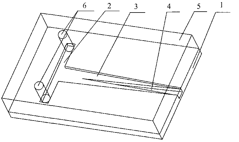
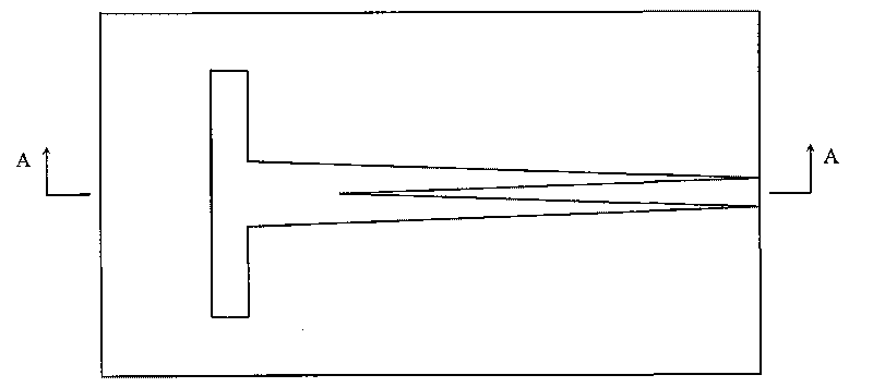
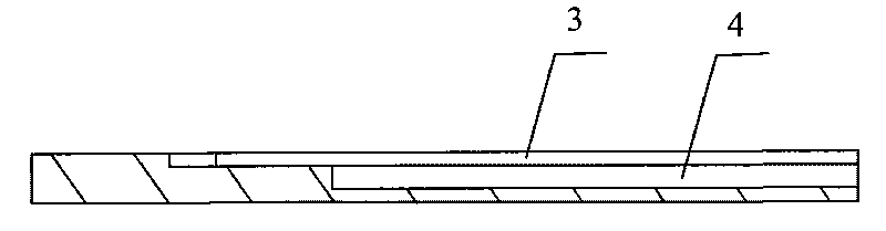
[0020] refer to Figures 1 to 3 , a micro-mixer in a chip, consisting of a PDMS substrate 1 and a glass plate 5 attached thereon, on the panel of the substrate 1 is provided with a transverse groove 2 and a connection with the outlet directly to the substrate The T-shaped groove formed by the longitudinal groove 3 at the plate end of the sheet 1, the longitudinal groove 3 is a tapered groove whose inlet width is greater than the outlet width connected to the transverse groove 2; A longitudinal inverted tapered groove 4 on the center line of the groove, the outlet width of the cone bottom of the inverted tapered groove 4 is equal to the outlet width of the longitudinal groove 3, and its tapered end reaches the entrance of the longitudinal groove 3 Rear part: through holes 6 communicating with the transverse groove 2 are respectively provi...


PUM


Abstract

The invention relates to a mixer for mixing micro-liquid, in particular to a chip-in micro-mixer for mixing micro-liquid in bio-detection, which consists of a PDMS (poly-dimethylsiloxane) substrate and a glass sheet pasted on the PDMS substrate, wherein a T-shaped groove is formed on the face plate of the substrate and composed of a transverse groove and a longitudinal groove communicated with the transverse groove; the outlet of the longitudinal groove is directly propped against the plate end of the substrate; the longitudinal groove is communicated with the transverse groove; the longitudinal groove is a conical groove with the inlet length larger than the outlet length; an inverted conical longitudinal groove parallel to the center line of the conical longitudinal groove is further formed on the bottom surface of the conical longitudinal groove; and through-holes for communicating the transverse groove are formed at two ends of the glass sheet corresponding to the transverse groove on the PDMS substrate. The invention effectively solves the difficult problems that the liquid in a micron-scale micro-channel has low flow rate, low Reynolds number and long mixing process, and the mixed liquid at the interface of the two liquids has an impact of blocking on the mutual intermolecular diffusion of the non-mixed liquid in the prior art.

Description

technical field [0001] The invention relates to a mixer for microfluidic mixing, in particular to a micromixing device integrated in a microfluidic chip suitable for microfluidic mixing in biological detection. Background technique [0002] The main purpose of the micro-mixer is to realize the rapid and thorough mixing of various trace reagents and samples before the biochemical reaction, and it is an important part of the microfluidic chip. According to the driving form, micro-mixers can be divided into active and passive types. Among them, active micro-mixers are easy to achieve rapid and uniform mixing of micro-liquids, but their accompanying drive units and moving parts are not conducive to integration with microfluidic chips. The passive micromixer has a simple structure, is easy to process, does not require external energy drive, and has no moving parts. Therefore, the passive mixer is more conducive to the integration with the microfluidic chip. There is an essential...

Claims


Application Information

Patent Timeline
Patent Type & Authority Applications(China)
IPC IPC(8): B01F5/00B01L3/00
Inventor 张平胡亮红吴一辉刘永顺邓永波
Owner CHANGCHUN INST OF OPTICS FINE MECHANICS & PHYSICS CHINESE ACAD OF SCI
Why Eureka
Try Eureka