Smoke-free gas burner

A technology of gas stove and no oil fume, applied in the field of gas stove, can solve the problems of heat loss, gas waste, pot weight, etc., and achieve the effect of preventing gas leakage, preventing the generation of oil fume, and ensuring personal safety

Inactive Publication Date: 2010-06-02
YONGCHANG INSTR & METER IND TIANTAI COUNTY
View PDF0 Cites 3 Cited by
  • Summary
  • Abstract
  • Description
  • Claims
  • Application Information

AI Technical Summary

Problems solved by technology

Therefore, when cooking, it is necessary to control the temperature in the pot to avoid oily smoke. At present, the common method of controlling the temperature in the pot is to increase the thickness of the pot, but this kind of pot is very heavy, and it is difficult to hold the pot with one hand when serving vegetables Pick it up, and control the temperature in the pot by thickening the pot wall so that the heat is lost in vain and gas is wasted

Method used


Image

  • Smoke-free gas burner
  • Smoke-free gas burner
  • Smoke-free gas burner

Examples


Embodiment 1

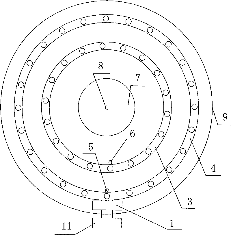
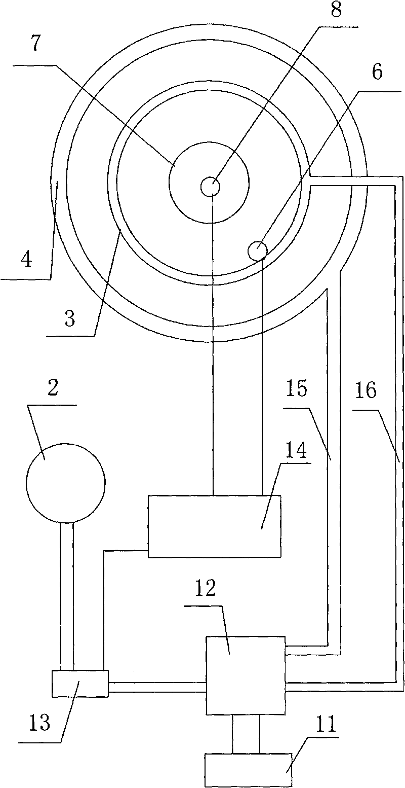
[0018] Such as figure 1 , figure 2 As shown, a fume-free gas stove includes a stove frame 9 provided with an ignition switch 11, inner and outer fire ring frames 3, 4 installed on the stove frame 9, and a liftable contact plate 7 located at the center of the stove frame 9 , the bottom of the contact plate 7 is provided with a spring or a lifting motor; the gas pipeline of the gas stove is provided with an ordinary valve 12 controlled by the ignition switch 11, and the ordinary valve 12 is fixed on the stove frame 9; the external gas source 2 of the gas pipeline is connected with the ordinary An electric control valve 13 that regulates the gas flow is installed between the valves 12. A single-chip microcomputer 14 that controls its work is connected to the electric control valve 13. The single-chip microcomputer 14 is connected with the ignition switch 11 that controls its working state. There is the first temperature sensor 8 that measures the temperature at the bottom of th...

Embodiment 2

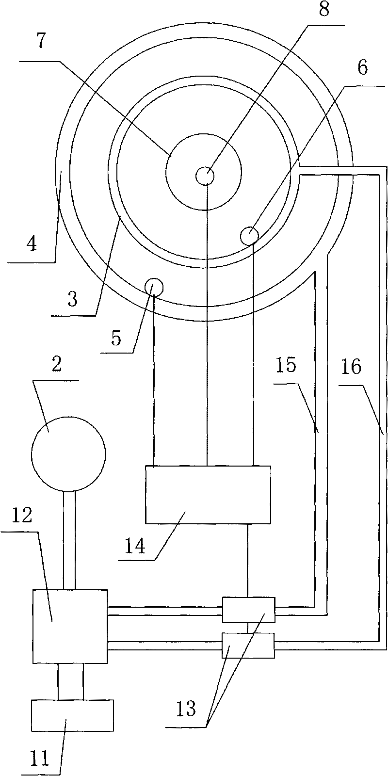
[0020] The structure of this embodiment is basically the same as that of Embodiment 1, the difference is that the electric control valve 13 is installed on the inner and outer fire ring gas pipes 16, 15 between the ordinary valve 12 and the inner and outer fire ring frames 3, 4 , the working principle of the control of oil fume in this embodiment is exactly the same as that of Embodiment 1; as for the control of preventing gas leakage, in addition to setting the second temperature sensor 6 on the inner fire ring frame 3 and its vicinity, the outer fire ring The frame 4 and its vicinity are provided with the third temperature sensor 5 connected with the single-chip microcomputer 14, and the single-chip microcomputer 14 can separately carry out the opening and closing of two electric control valves 13 on the inner and outer fire ring gas pipes according to the temperature near the inner and outer fire rings. control.

Embodiment 3

[0022] The structure of this embodiment is basically the same as that of Embodiment 1, the difference is that the electric control valve is composed of a common valve 12 on the gas pipeline and a servo motor 17 installed on the common valve 12 and controlling its flow. The single-chip microcomputer 14 of its work is connected.


PUM


Abstract

The invention relates to a smoke-free gas burner, comprising a burner frame provided with a lighting switch, an inner fire ring frame and an outer fire ring frame arranged on the burner frame, normal valves adjusted by lighting switch is arranged on the gas pipeline, wherein the normal valves are fixed on the burner frame, and the gas pipeline of the gas burner is provided with an intelligent flux control system of which the gas flux is adjusted according to the temperature of the boiler bottom; the smoke-free gas burner utilizes the intelligent flux control system to control gas flux to ensure that the temperature of the boiler bottom is between the critical temperature of cooked food and the critical temperature for generating smoke, thus guaranteeing food to be cooked in time, resisting the generation of smoke, and ensuring the health of the user.

Description

technical field [0001] The invention belongs to the technical field of gas stoves, and relates to a fume-free gas stove. Background technique [0002] According to experts' verification, there is a direct relationship between cooking fume and the temperature of the cooking oil: when the oil is heated above 200°C, acrolein, the main component of cooking fume, has a strong spicy taste and has a strong effect on the mucous membranes of the nose, eyes and throat. When the oil is burned to "spit fire", the oil temperature exceeds 300°C, at this time, in addition to producing acrolein, it will also produce aggregates, leading to chronic poisoning. It is easy to induce respiratory and digestive system cancers. Therefore, when cooking, it is necessary to control the temperature in the pot to avoid oily smoke. At present, the common method of controlling the temperature in the pot is to increase the thickness of the pot, but this kind of pot is very heavy, and it is difficult to hol...

Claims


Application Information

Patent Timeline
IPC IPC(8): F24C3/12
Inventor 赵光天
Owner YONGCHANG INSTR & METER IND TIANTAI COUNTY
Why Eureka
Try Eureka