Eureka AIR delivers breakthrough ideas for toughest innovation challenges, trusted by R&D personnel around the world.

Exhaust gas fume afterheat recovering system with heat-accumulating and temperature-equalizing equipment

A waste heat recovery system and flue gas waste heat technology are applied in the fields of treatment, waste heat recovery, and flue gas dust removal. It can solve the problems of large horse-drawn carts and low steam production, and achieve the effects of improving efficiency, reducing investment, and reducing the amount of mixed cold air.

Inactive Publication Date: 2010-06-02
无锡市东方环境工程设计研究所
View PDF0 Cites 3 Cited by
  • Summary
  • Abstract
  • Description
  • Claims
  • Application Information

AI Technical Summary

Problems solved by technology

However, the actual steam output is far lower than the maximum evaporation capacity of the waste heat system, resulting in the situation of large horses and small carts

Method used


Image

  • Exhaust gas fume afterheat recovering system with heat-accumulating and temperature-equalizing equipment
  • Exhaust gas fume afterheat recovering system with heat-accumulating and temperature-equalizing equipment
  • Exhaust gas fume afterheat recovering system with heat-accumulating and temperature-equalizing equipment

Examples


Embodiment 1

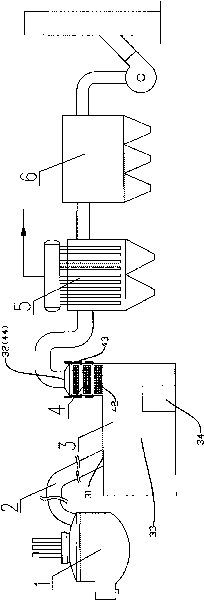
[0026] Such as figure 1 As shown, the waste heat recovery system in this embodiment includes a settling chamber 3, heat storage and temperature equalization equipment 4, waste heat recovery device 5 and dust collector 6 arranged in sequence, wherein the heat storage and temperature uniformity equipment 4 is set in the settling chamber 3 and the waste heat recovery device 5, the heat storage uniform temperature equipment 4 includes a flue gas inlet 41, a heat storage body 42, a dust removal device 43, a flue gas outlet 44 and an ash hopper 45, and the heat storage body 42 is arranged on the flue gas Between the gas inlet 41 and the flue gas outlet 44, the arrangement is vertical or horizontal; the ash removal device 43 is arranged between the regenerators 42 in sections; the flue gas inlet 41 and the flue gas The outlet 44 is respectively connected with the flue gas outlet 32 ​​of the settling chamber 3 and the flue gas inlet 51 of the waste heat recovery device 5 .

Embodiment 2

[0028] Such as figure 2 As shown, the difference between this embodiment and Embodiment 1 is that the heat storage uniform temperature equipment 4 is arranged in the settling chamber 3, and is integrated with the settling chamber to form a heat storage uniform temperature settling chamber. The warm settling chamber includes a flue gas inlet 31, a settling flue 33, a heat storage body 42, a dust removal device 43, a flue gas outlet 34 (44), and a dust removal door 34, wherein the heat storage body 42 is arranged in the settling chamber 3 There are 34 flue gas outlets.

Embodiment 3

[0030] Such as image 3 As mentioned above, the difference between this embodiment and Embodiment 1 is that: the heat storage and uniform temperature equipment 4 is set in the waste heat recovery device 5, and is integrated with the waste heat recovery device 5 to form a heat storage and uniform temperature waste heat recovery device. The heat uniform temperature waste heat recovery device includes a flue gas inlet 41 (51), a heat storage body 42, a dust removal device 43, a heat exchanger 53, a flue gas outlet 52 and an ash hopper 45, wherein the heat storage body 4 is arranged on the waste heat The flue gas inlet 51 of the recovery device 5.

[0031] Of course, the present invention can also have other implementations, for example, the waste heat recovery device 5 can also be a flue gas cooling device.

[0032] When used, such as Figure 1-3 As shown, the high-temperature flue gas generated in the electric furnace 1 is heat-exchanged through the cooling water pipeline (her...


PUM


Abstract

The invention relates to an afterheat recovering system, in particular to an exhaust gas fume afterheat recovering system with heat-accumulating and temperature-equalizing equipment, which comprises a settling chamber, the heat-accumulating and temperature-equalizing equipment, an afterheat recovering device and a dust catcher which are sequentially arranged, wherein the heat-accumulating and temperature-equalizing equipment can be independent, can also be integrated with the settling chamber to form a heat-accumulating, temperature-equalizing and settling chamber, and can also be integrated with the afterheat recovering device to form a heat-accumulating, temperature-equalizing and afterheat recovering device. Because of the heat-accumulating and temperature-equalizing equipment, the exhaust gas fume afterheat recovering system of the invention can clip a peak to fill a trough of a gas fume temperature, decrease the maximum temperature of gas fume, reduce a fluctuation amplitude of the gas fume temperature and release drastic rising and dropping of the gas fume temperature, thereby reducing investment of an afterheat system or a gas fume cooling device, improving the stability of the afterheat system and safely allocating various heat exchangers.

Description

technical field [0001] The invention relates to a waste heat recovery system, in particular to a waste heat recovery system for flue gas exhausted in an electric furnace with heat storage and uniform temperature equipment, and belongs to the technical field of flue gas dust removal, treatment and waste heat recovery. Background technique [0002] The iron and steel industry consumes a large amount of energy every year, and the high-temperature flue gas generated during the smelting process and the heat dissipation of equipment take away a large amount of energy. Due to the drastic fluctuations in the temperature of the exhaust gas in the electric furnace and the large amount of dust, it is difficult for ordinary water tube waste heat boilers to be used in the waste heat recovery of the exhaust gas in the electric furnace. At present, the heat pipe waste heat recovery system has been successfully applied to the waste heat recovery of the flue gas of the electric furnace. Pop...

Claims


Application Information

Patent Timeline
IPC IPC(8): F27D17/00
CPCY02P10/25
Inventor 张鹏何先志
Owner 无锡市东方环境工程设计研究所
Why Eureka
Eureka Blog
Learn More