
Phase-shift white light interferometry method based on 3*3 optical fiber coupler

A technology of optical fiber coupler and white light interference, which is applied in the field of optical fiber sensing, achieves the effects of large dynamic range, high-speed absolute measurement and high precision

Inactive Publication Date: 2010-06-02
BEIJING INSTITUTE OF TECHNOLOGYGY
View PDF1 Cites 22 Cited by
  • Summary
  • Abstract
  • Description
  • Claims
  • Application Information

AI Technical Summary

Problems solved by technology

[0011] The purpose of the present invention is to better solve the problem of fast and efficient demodulation of the absolute optical path difference of the interferometer, and propose a simple and high-speed method to measure the absolute optical path difference of the optical fiber interferometer, which has high precision, fast speed, and absolute Advantages such as measurement

Method used


Image

  • Phase-shift white light interferometry method based on 3*3 optical fiber coupler
  • Phase-shift white light interferometry method based on 3*3 optical fiber coupler
  • Phase-shift white light interferometry method based on 3*3 optical fiber coupler

Examples


Embodiment Construction

[0032] specific implementation plan

[0033] The present invention will be further described below in conjunction with the accompanying drawings and embodiments.

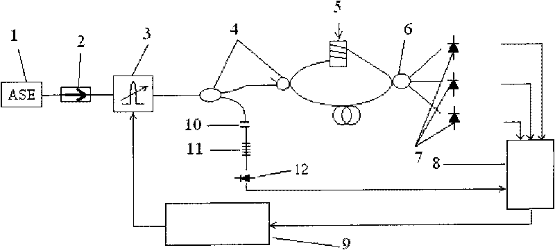
[0034] The measurement method of the present invention is verified through experiments. figure 1 It is an implementation schematic diagram of the method of the present invention, and the method of the present invention is described in conjunction with the measurement of the optical path difference between the two arms of the Mach-Zehnder interferometer.

[0035] The light emitted by the broadband light source 1 is input to the fiber tunable F-P filter 3 through the optical isolator 2, and the fiber-tunable F-P filter 3 is driven by the sawtooth wave generator 9 to output the wavelength-scanning narrow-band light, and the wavelength-scanning narrow-band light is The 2×2 coupler 4 is divided into two paths, one of which passes through the Fap etalon 10, the fiber grating 11, and the photodetector 12 to detect the tra...


PUM


Abstract

The invention relates to an optical fiber white light interferometry method, in particular to a phase-shift white light interferometry method based on a 3*3 optical fiber coupler, belonging to the technical field of optical fiber sensing. A 2*2 optical fiber coupler and a 3*3 optical fiber coupler form an optical fiber M-Z interferometer, and a wavelength scanning light is injected into the optical fiber M-Z interferometer. Magnitudes of three paths of output white light interference spectrum signals are equal, and an angle of 120 degrees is formed between every two paths of output white light interference spectrum signals on the phase. When the wavelength scanning light scans from Lambda 1 to Lambda 2, three paths of output signals I1, I2 and I3 are obtained, and Delta is demodulated through computing or constructing two paths of orthorhombic signals and utilizing a derivation cross multiplying method. The Delta is subjected to the unwrapping operation to demodulate linear phase information after computed. The absolute optical path difference of the interferometer can be computed by using the linear phase information. The invention can absolutely measure the optical path difference of the optical fiber interferometer with high precision and high speed.

Description

technical field [0001] The invention relates to an optical fiber white light interferometry method, in particular to a phase shift white light interferometry method based on a 3×3 optical fiber coupler, and belongs to the technical field of optical fiber sensing. Background technique [0002] Interferometric fiber optic sensors, such as Fabry-Perot (Fabry-Perot), Mach-Zehnder (Mach-Zehnder), Michelson (Michelson), Sagnac (Sagnac), etc., have high Measurement sensitivity is widely used. To be measured, such as strain, temperature, displacement or pressure, etc., act on the interferometer, causing the change of the optical path difference of the interferometer, and demodulating the optical path difference from the output interference signal of the interferometer, so as to realize the measurement of the measured physical quantity . [0003] Interferometry is a very important method for measuring many parameters (such as temperature, pressure, strain, etc.), often using one ar...

Claims


Application Information

Patent Timeline
Patent Type & Authority Applications(China)
IPC IPC(8): G01D5/353G01J9/02
Inventor 江毅梁蓬娟
Owner BEIJING INSTITUTE OF TECHNOLOGYGY
Learn More