Fluorescent-lamp-type led lighting device

A LED lighting and transparent technology, which is applied in lighting devices, parts of lighting devices, lighting and heating equipment, etc. It can solve the problems of adding electrodes, hindering the injection efficiency, increasing the light quantization, and reducing the amount of light emitted, so as to achieve the effect of suppressing heat generation

Inactive Publication Date: 2010-06-02
ABEL SYST
View PDF3 Cites 2 Cited by
  • Summary
  • Abstract
  • Description
  • Claims
  • Application Information

AI Technical Summary

Problems solved by technology

However, since the electrode is attached to the surface of the element, and the electrode blocks light, the improvement of the output efficiency of the light to the outside and the large light quantization due to the increase in area are hindered.
However, in order to reduce the influence of light shielding, if the area of ​​the electrode is reduced by a certain value or more compared to the area of ​​the element, the same electric field cannot be applied to the entire element, and the amount of light emitted itself will also decrease.
Therefore, even if the area of ​​the element is increased in order to obtain a large amount of light, the area of ​​the electrode must be increased to make it emit light from the surface, and a large amount of light cannot be emitted to the outside due to the light-shielding effect of the electrode.
In addition, in view of such disadvantages, it is considered to use a transparent electrode such as ITO, but the resistance of the transparent electrode is higher than that of the metal electrode, so loss occurs in this part and the luminous efficiency decreases.

Method used


Image

  • Fluorescent-lamp-type led lighting device
  • Fluorescent-lamp-type led lighting device
  • Fluorescent-lamp-type led lighting device

Examples


Embodiment Construction

[0029] Below, refer to Figure 1 to Figure 9 One embodiment of the present invention will be described.

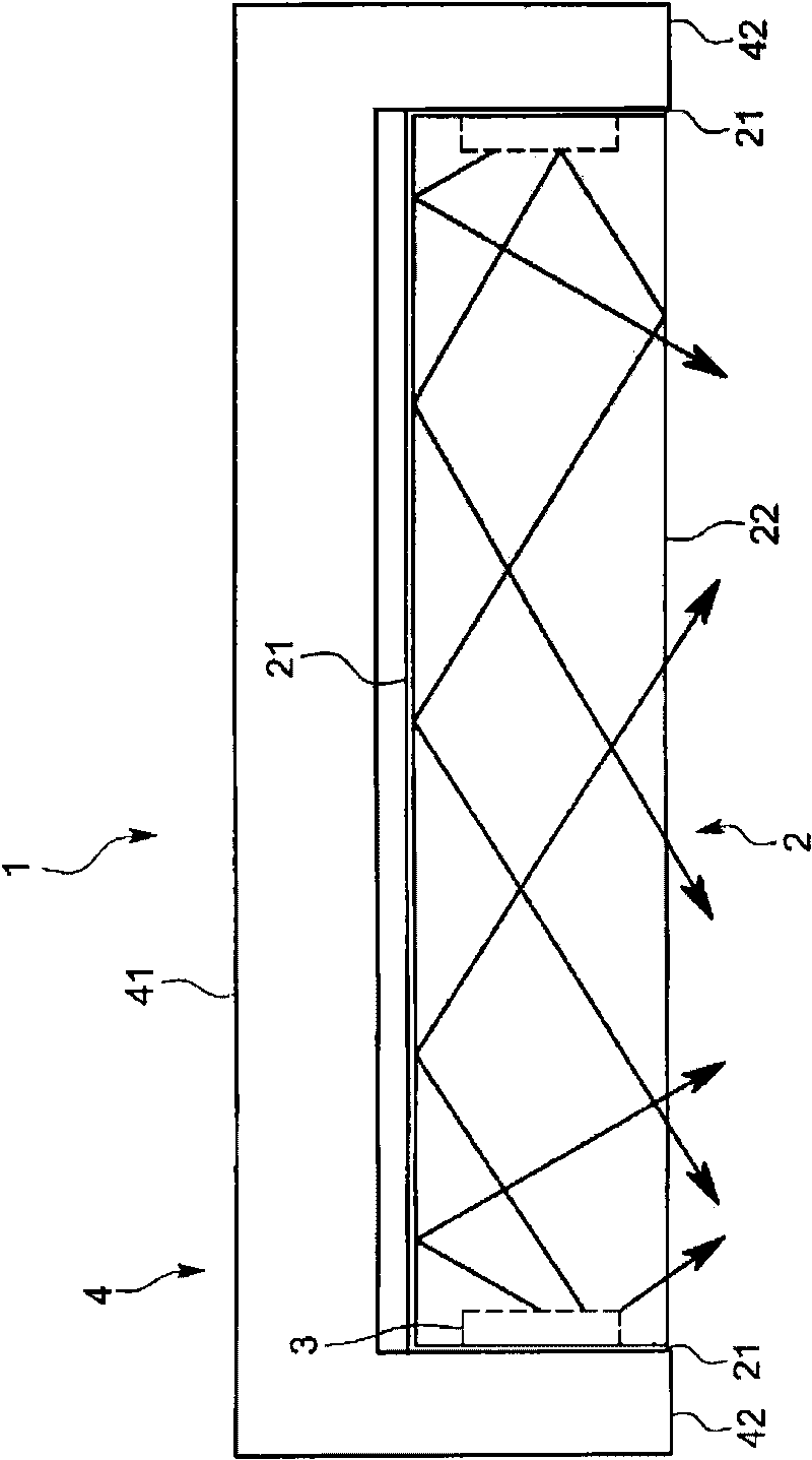
[0030] The LED lighting device 1 of this embodiment is used for general lighting such as indoor lighting instead of fluorescent lamps, for example, figure 1 As shown, it includes: an exterior body 2; an LED3 mounted on the exterior body 2; a holder 4 for holding the exterior body 2 and the LED3.

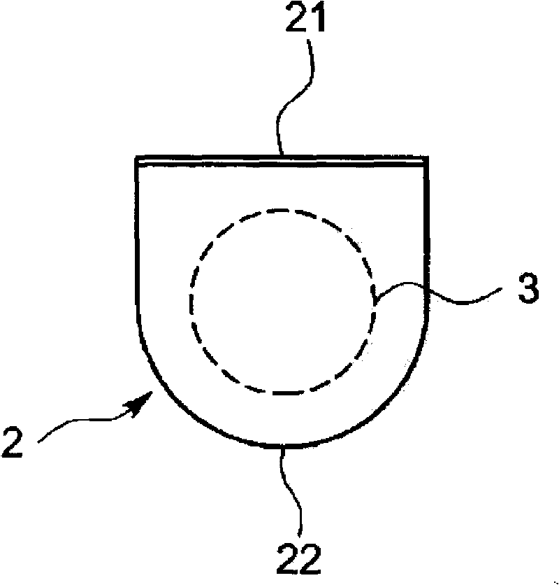
[0031] The exterior body 2 is a transparent member made of resin and has a columnar shape, and its cross section is, for example, figure 2 Shown is a roughly semicircular shape. In this embodiment, reflectors 21 facing inward are attached to both end faces and the flat parts of the side peripheral surfaces of the exterior body 2, and the light introduced into the interior of the exterior body 2 from the LED 3 described later is not provided with the reflectors 21. The side peripheral surface of the cylindrical outer surface 22 shoots out.

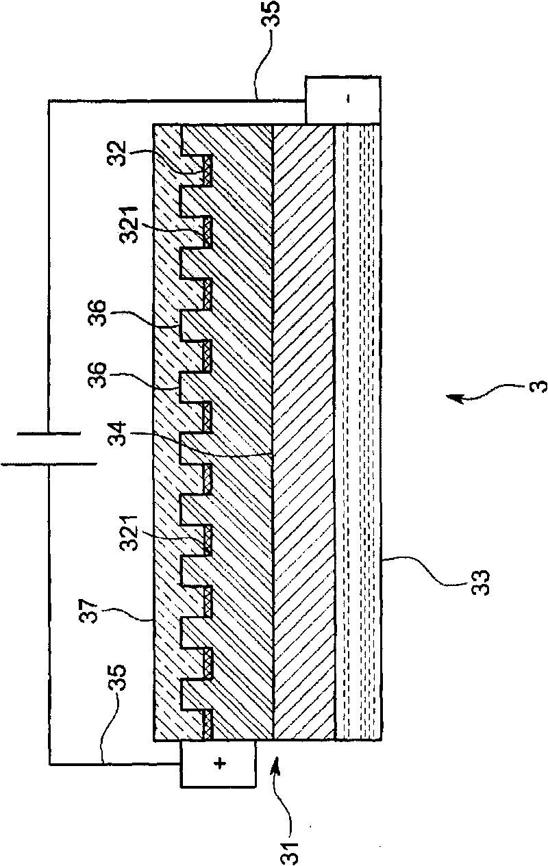
[0032] LED3 as image 3 As shown,...


PUM


Abstract

A fluorescent-lamp-type LED lighting device includes an LED (3) including a thin plate-like semiconductor element body (31) for transmitting light generated in a PN junction region (34) in the thickness direction for emitting from a surface, a surface electrode (32) provided to cover the surface of the element body (31) and a plurality of cylindrical dielectric antennas (36) for condensing the light which has passed through the surface electrode (32) in the thickness direction and transmitted through the inside of the element body (31) and emitting it outside, and a resin-made elongate exterior casing (2) having translucency. The LED (3) is provided at both ends of the exterior casing (2) or along its longitudinal direction. The lighting device is structured to shed the light emitted from the LED (3) outside through the exterior casing (2), has a large light quantity and can substitute for a highly efficient existing lighting device.

Description

technical field [0001] The present invention relates to a strip-shaped fluorescent lamp type LED illuminating device using high-efficiency LED capable of emitting surface light. Background technique [0002] Compared with fluorescent lamps and incandescent lamps, LEDs have a long life and stable light intensity, and there are few cases where it takes time to start up and causes problems in disposal. And recently, in addition to the development of LEDs that emit blue light and ultraviolet light, high-power LEDs have also been developed. LEDs are not only used in indicators as in the past, but are also being used in general lighting equipment. [0003] However, if the total light quantity, illuminance, etc. are compared, although the light quantity per unit light-emitting area increases, LEDs are not as good as fluorescent lamps. In order to obtain the same amount of light as a fluorescent lamp as a whole, many LEDs are required, and thus the heat generation becomes very larg...

Claims


Application Information

Patent Timeline
Patent Type & Authority Applications(China)
IPC IPC(8): F21V3/00H01L33/00H01L33/20H01L33/38H01L33/50
CPCF21K9/00F21K9/30H01L33/20F21Y2103/003G02B6/0055H01L33/382G02B6/0073H01L33/508F21K9/20F21Y2103/10F21Y2115/10
Inventor 铃木文雄
Owner ABEL SYST
Why Eureka
Try Eureka