
Continuous feeding device for alumina

A technology of feeding device and alumina, which is applied in the field of continuous alumina feeding device for pre-baked aluminum electrolytic cells, can solve the problems of imbalance, increase carbon fluoride gas emission, increase power consumption and material consumption of electrolytic aluminum, and achieve stable stability Balance, reduce power consumption, reduce emissions

Inactive Publication Date: 2010-06-09
高德金
View PDF0 Cites 20 Cited by
  • Summary
  • Abstract
  • Description
  • Claims
  • Application Information

AI Technical Summary

Problems solved by technology

[0004] This kind of time-point interval and quantitative feeding prebaked aluminum electrolytic cell feeding device that is now commonly used, although from the perspective of material balance, strives to meet the requirements by increasing the number of times of feeding, shortening the feeding interval, and reducing the amount of feeding at constant volume. Electrolytic cells, especially large-scale prebaked electrolytic cells, need to balance the electrolyte alumina concentration and materials. However, due to the design of the mechanical device, the wear of the shelling hammer, the wind pressure of the shelling cylinder, and the thickness of the crust on the surface of the electrolytic cell change , Abnormal changes in the concentration of electrolytic alumina, the adjustment of process parameters and other conditional factors, it is difficult for the current general-purpose aluminum electrolytic cell feeding device to realize the organic unity of the feeding method and amount of feeding and the electrolysis process to achieve an ideal state, resulting in electrolytic cells The imbalance of the electrolyte alumina concentration in the thermoelectrochemical electrolysis reaction process of the electrolyte and alumina in the electrolysis process affects the stable balance of various electrolysis process parameters in the electrolysis process, which not only increases the power consumption and material consumption of electrolytic aluminum, but also reduces the efficiency. , and increase the number of effects of the electrolytic cell, increase the emission of fluorinated carbon gas, and cause environmental pollution

Method used


Image

  • Continuous feeding device for alumina
  • Continuous feeding device for alumina
  • Continuous feeding device for alumina

Examples


Embodiment Construction

[0013] The concrete embodiment of shelling device for aluminum electrolytic cell of the present invention is:

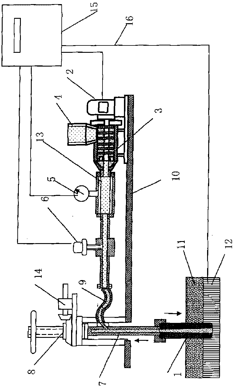
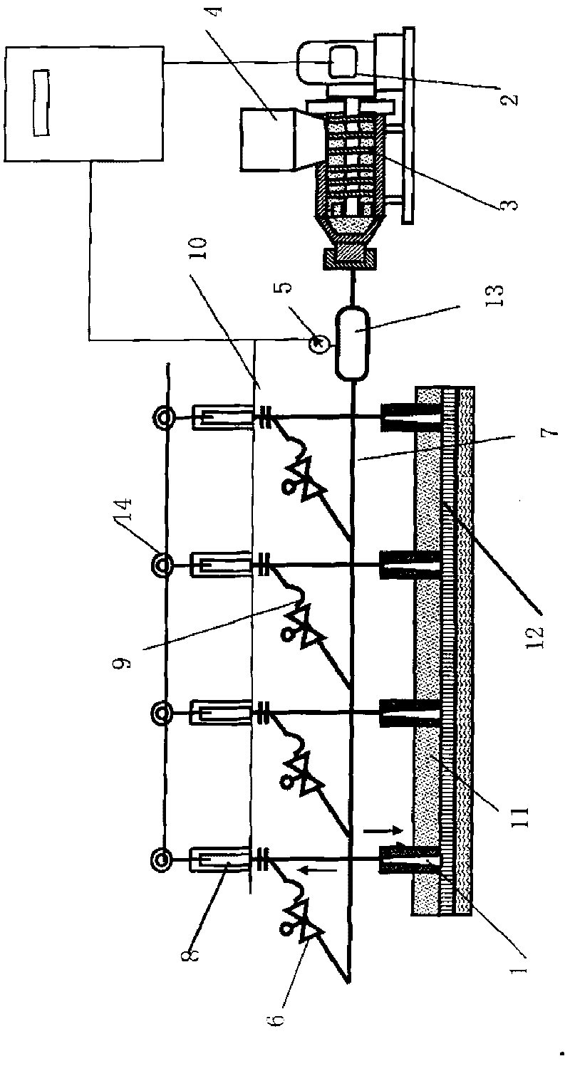
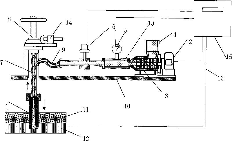
[0014] The alumina continuous feeding device consists of injection pipe (1), pressurized pump frequency conversion motor (2), alumina pressurized pump (3), feeding box (4), pipeline pressure relay meter (5), flow control valve (6 ), conveying pipeline (7), lifting and pressing device (8), and connecting parts are constructed.

[0015] On the upper structure of the electrolytic cell (10), the lifting and pressing device (8) of the alumina powder injection pipe (1) is set, so that the alumina powder injection pipe (1) passes through the alumina crust (11), It is in liquid communication with the electrolyte (12), and the variable frequency booster pump (3) is used to drive the variable frequency booster pump (3) to pressurize the alumina powder, and the sealed delivery pipe (7) and delivery hose (9) are used to pass through the injection pipe (1), continuously injected...


PUM


Abstract

The invention discloses a continuous feeding device for alumina. In the structure of the device, an upper structure of an electrolytic cell is provided with an upper alumina powder spray pipe lifting and pressing device to allow an alumina powder spray pipe to pass through electrolyte and alumina crust to be communicated with electrolyte; a pressure pump is used to pressurize the alumina powder; in a sealed delivery pipe, the pressure pump and a flow control valve are controlled by a command sent by a computer in a cell control cabinet of the electrolytic cell to adjust the pressure, volume and flow rate for delivering the alumina powder; and thus, the alumina powder can be continuously injected into the electrolyte from the delivery pipe and the spray pipe.

Description

Technical field: [0001] The invention relates to an alumina continuous feeding device for a prebaked aluminum electrolytic cell. Background technique: [0002] The current general prebaked aluminum electrolytic cell feeding device is composed of pneumatic chute, constant volume feeder, shelling cylinder, guide connecting rod, shelling hammer and other components. The voltage signal generated by the chemical change with the concentration of alumina and the time difference of the material balance are used to control the action of the electromagnetic reversing valve, and to control the up and down movement of the piston rod in the shelling cylinder. The hammer head is driven by the guide connecting rod to break The electrolyte crust is composed of electrolyte and alumina, and after forming an alumina feeding channel, quantitatively add alumina to the electrolyte of the electrolytic cell to maintain the balance of the concentration of alumina in the electrolyte, participate in t...

Claims


Application Information

Patent Timeline
IPC IPC(8): C25C3/14
Inventor 高德金高伟
Owner 高德金
Learn More