Novel house wall

A new type of house and wall technology, applied in the direction of walls, building components, insulation, etc., can solve problems such as deflection, low seismic strength of house walls, poor stability, etc., to ensure wall strength, expand the use range, and sound insulation effect Improved effect

Inactive Publication Date: 2010-06-09
郭育志 +1
View PDF0 Cites 2 Cited by
  • Summary
  • Abstract
  • Description
  • Claims
  • Application Information

AI Technical Summary

Problems solved by technology

[0006] However, in the above-mentioned composite structure, because the slanting wire 30 straddles obliquely between the two mesh sheets 10, and each slanting wire 30 spans two pairs of grids (the first grid 101, the second grid 102) ,like figure 2 , 3 As shown, one end of the oblique insertion wire 30 is welded on the first mesh 101 of the first mesh 10, and the other end is welded on the second mesh 102 next to the first mesh 101 opposite to the second mesh 10, wherein , figure 2 The same row of oblique insertion wires 30 shown is arranged next to each other, image 3 The same row of slanting wires 30 is arranged at intervals of a grid, and the slanting direction of the slanting wires 30 in the same row is the same, and the slanting direction of the slanting wires 30 in an adjacent row is opposite, and the inclination angle of the slanting wires 30 is not easy to be too large Or too small, generally at 40 to 60 degrees (this structure has the strongest strength and the highest seismic strength), so that the center distance of the mesh 10 can usually only be less than 6 cm. If the center distance of the mesh 10 is to be increased, due to If the grid size is fixed, the inclination angle can only be increased, which will cause the grid structure to be weak and the seismic strength of the wall to be low, which cannot meet the building requirements. For interior walls or other places with low requirements for sound insulation, heat insulation and heat preservation, the scope of use is limited
[0007] In addition, in the above-mentioned composite structure, the solder joints of two adjacent rows of obliquely inserted wires 30 on the same mesh 10 are aligned up and down, such as figure 2 , 3 The upper and lower solder joints are superimposed together as shown in the top view, such a grid structure is prone to deflection, poor stability, and the seismic strength of the made house wall is low

Method used


Image

  • Novel house wall
  • Novel house wall
  • Novel house wall

Examples


Embodiment Construction

[0034] Such as Figure 4 and Figure 5 Shown is a preferred embodiment of the present invention.

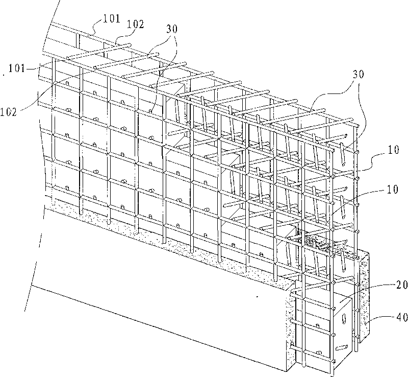
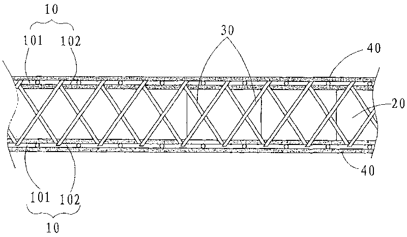
[0035] A new type of house wall disclosed in this embodiment is welded with steel wires to form two mesh sheets 1, and the grids of the two mesh sheets 1 are opposite to each other. A foam board 2 is filled between the two mesh sheets 1 . There are also oblique wires 3 between the two meshes 1, the oblique wires 3 are interspersed on the foam board 2 and the two ends are respectively welded on the two meshes 1, the oblique wires 3 are located in the same row in the same direction of inclination, The inclination directions of two adjacent rows are opposite. A cement mortar layer 4 is applied on the two mesh sheets 1 . The invention also has the advantages of heat insulation, high strength, shock resistance, moisture and fire prevention, sound insulation, light weight, and convenient architectural design.

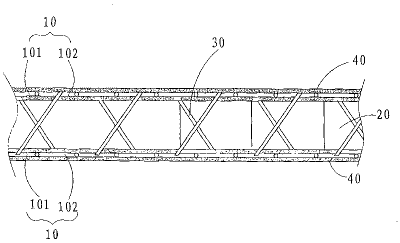
[0036] The improvements of the present invention are as Figure 5 As ...


PUM


Abstract

The invention discloses a novel house wall. Two net sheets are formed by welding steel wires; meshes of the two net sheets are two-two opposite; a foam board is packed between the two net sheets; inclined inserted wires are also arranged between the two net sheets; the inclined inserted wires are inserted on the foam board; two ends of the inclined inserted wires are welded onto the two net sheets respectively; cement mortar layers are smeared on the two net sheets, wherein each inclined inserted wire spans a first mesh of one net sheet and a third mesh of the other net sheet, namely one end of the inclined inserted wire is welded onto the first mesh of a first net sheet, and the other end of the inclined inserted wire is welded onto the third mesh of a second net sheet which is opposite to the first mesh and is at a one-mesh interval. The structure is applicable to a bearing / non-bearing inner / outer wall and all other buildings having high requirement for heat insulating-preserving effect, thereby expanding application range.

Description

technical field [0001] The invention relates to the technical field of building materials, in particular to a new type of house wall with heat insulation, high strength, shock resistance, sound insulation, moisture resistance and fire prevention, and light weight. Background technique [0002] With the development of science and technology and the requirements of environmental protection, various new building materials are gradually being widely used, such as figure 1 The house wall shown is one of these. [0003] The house wall is welded into two mesh sheets 10 with steel wires, the grids of the two mesh sheets 10 are opposite to each other, and a foam board 20 of self-extinguishing polystyrene foam is filled between the two mesh sheets 10. The foam board 20 has the effect of heat insulation and sound insulation. There is also an oblique insertion wire 30 between the two mesh sheets 10. The oblique insertion wire 30 is inserted on the foam board 20 and the two ends are res...

Claims


Application Information

Patent Timeline
IPC IPC(8): E04B2/00E04B1/88E04B1/94E04B1/98
Inventor 郭育志冯左
Owner 郭育志
Why Eureka
Try Eureka