Dry wet-type drill box of anchor rod drill carriage
What is Al technical title?
Al technical title is built by PatSnap Al team. It summarizes the technical point description of the patent document.
A bolter drilling rig, dry and wet technology, applied in the installation of bolts, drilling equipment, earthwork drilling and production, etc., can solve the problems of large drilling rig vibration, potential safety hazards, poor drilling quality, etc.
Active Publication Date: 2012-06-27
TAIYUAN INST OF CHINA COAL TECH & ENG GROUP +1
View PDF0 Cites 0 Cited by
Summary
Abstract
Description
Claims
Application Information
AI Technical Summary
This helps you quickly interpret patents by identifying the three key elements:
Problems solved by technology
Method used
Benefits of technology
Problems solved by technology
[0002] In the roadway excavation under the coal mine, in order to prevent the roadway from collapsing, it is necessary to support the roof and both sides of the roadway. There are many types of support, but the most used is the bolt support. In order to install the bolt, it must be installed in the roadway. Drilling is carried out on the wall, and some use artificial drilling rigs for drilling. However, due to the large vibration of the drilling rig and the large swing of the drill pipe, the drilling position is difficult to grasp, and it is easy to deviate. The drilling quality is not high, the efficiency is low, and there are safety hazards
[0003] In large and medium-sized coal mines, bolters are often used for mechanized drilling, but some drilling rigs equipped with bolters have insufficient performance, low power, many mechanical failures, and cannot drill under dry and wet dust removal conditions at the same time. hole, this technology still needs further improvement
Method used
Image
Click on the blue label to locate the original text in one second.
Reading with bidirectional positioning of images and text.
Examples
Embodiment Construction
[0021] The present invention will be further described below in conjunction with accompanying drawing:
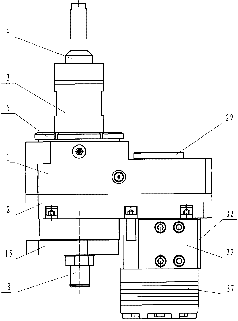
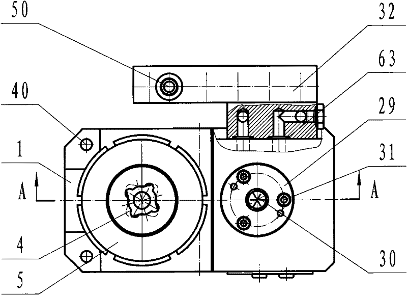
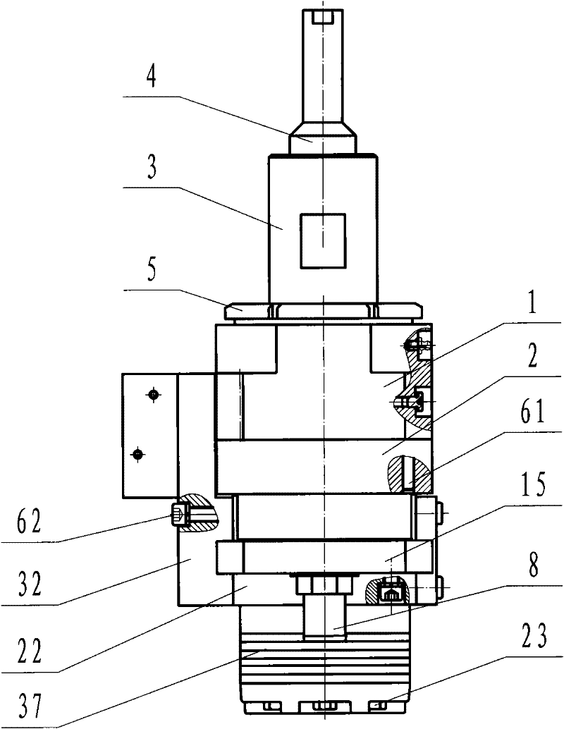
[0022] figure 1 , 2 , 3, and 4 show the overall structure diagram, the position and connection relationship of each part must be correct, and the installation should be firm.
[0023] The upper and lower boxes, lower end cover, hydraulic motor connection block, liquid distribution plate, hydraulic motor, and upper end cover must be strictly sealed to prevent oil leakage.
[0024] The upper part is the drill pipe, the lower part is the water and air pipe joint, and the right part is driven by the hydraulic motor, forming a fully sealed structure, which can prevent dust and water mist, and can be drilled under dry dust removal and sprayed. Wet drilling.
[0025] The gear of the hydraulic motor shaft and the gear of the transmission shaft are in a 1:1 transmission connection.
[0026] Figure 5 , 6 As shown, it is the structural diagram of the liquid distribution plate. ...
PUM
Abstract
The invention relates to a dry wet-type drill box of an anchor rod drill carriage, which mainly consists of an upper box body, a lower box body, a transmission shaft, a drill bushing, a drill rod, a water seal, a locking disc, a lower end cover, a framework sealing seat, a floating seal, a hydraulic motor, a hydraulic motor connecting block, a liquid preparing plate, a hydraulic motor shaft gear,a transmission shaft gear and a bearing; wherein the drill box can be used in both a dry dedusting state and a wet dedusting state of the anchor rod drill carriage, and takes the cycloid hydraulic motor as power to drive the hydraulic motor shaft gear and the transmission shaft gear to rotate, thus driving the drill bushing and the drill rod to drill holes. By adopting full-sealing structure and combining framework seal, the floating seal, a sealing ring and the water seal, the drill box prevents dry-type boring dust from entering and prevents dust-containing water of wet-type atomizing boring dust removal from entering, thus leading the drill box to have drilling operation in a full-closed state. The drill box is advanced and reasonable in design, compact in structure, convenient in use and installation, safe, stable and reliable, and has dual purposes of dry and wet dust removal and good universality, thus being an ideal drill box of the anchor rod drill carriage and used on similarequipment.
Description
technical field [0001] The invention relates to a wet and dry drilling box of a rock bolter, belonging to the technical field of design and manufacture of components of a rock bolter in a coal mine. Background technique [0002] In the roadway excavation under the coal mine, in order to prevent the roadway from collapsing, it is necessary to support the roof and both sides of the roadway. There are many types of support, but the bolt support is the most used. In order to install the bolt, it must be installed in the roadway. Drilling is carried out on the wall, and some use artificial drilling rigs for drilling. However, due to the large vibration of the drilling rig and the large swing of the drill pipe, the drilling position is difficult to grasp, and it is easy to deviate. The drilling quality is not high, the efficiency is low, and there are safety hazards . [0003] In large and medium-sized coal mines, bolter rigs are often used for mechanized drilling, but some rigs ...
Claims
Application Information
Patent Timeline
Application Date:The date an application was filed.
Publication Date:The date a patent or application was officially published.
First Publication Date:The earliest publication date of a patent with the same application number.
Issue Date:Publication date of the patent grant document.
PCT Entry Date:The Entry date of PCT National Phase.
Estimated Expiry Date:The statutory expiry date of a patent right according to the Patent Law, and it is the longest term of protection that the patent right can achieve without the termination of the patent right due to other reasons(Term extension factor has been taken into account ).
Invalid Date:Actual expiry date is based on effective date or publication date of legal transaction data of invalid patent.