Laser propulsion device

A propulsion device and laser technology, applied in jet propulsion devices, rocket engine devices, machines/engines, etc., can solve problems such as small specific impulse ratio theoretical value, mass loss, etc., to improve actual specific impulse, prolong life, and avoid heat conduction Effect

Inactive Publication Date: 2010-06-16
INST OF PHYSICS - CHINESE ACAD OF SCI
View PDF0 Cites 32 Cited by
  • Summary
  • Abstract
  • Description
  • Claims
  • Application Information

AI Technical Summary

Problems solved by technology

However, previous experimental studies usually use laser pulses to directly irradiate solid propellants to generate high-speed plasma jets. The problem is that part of the solid propellant is vaporized or splashed due to the heat conduction effect of the solid propellant. The shot breaks away from the surface of the solid propellant at a very low speed, causing a part of the mass loss, and the obtained specific impulse is much smaller than the theoretical value

Method used


Image

  • Laser propulsion device
  • Laser propulsion device
  • Laser propulsion device

Examples


Embodiment 1

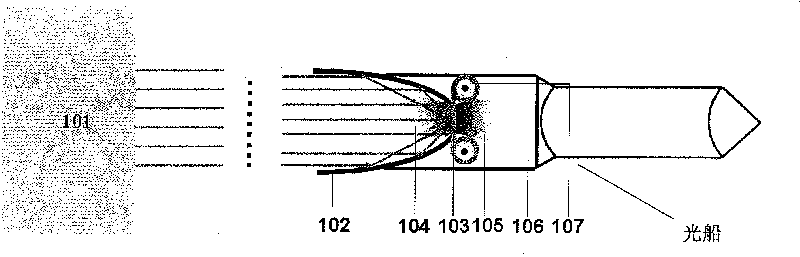
[0024] figure 1 It is a schematic diagram of a laser propulsion device according to an embodiment of a thin film propellant used in the present invention, the device includes a pulsed laser 101, a parabolic mirror 102, a combustion chamber 106 and a belt conveyor 107; wherein the belt conveyor is used for not Thin-film propellant 103 is provided intermittently, said thin-film propellant is located in the opening at the top of parabolic mirror 102, and is located at the focal point of parabolic mirror 102, so that said parabolic mirror can focus laser light onto the thin-film propellant. Preferably, the thickness of the thin film propellant is less than or equal to the ablation depth of the laser pulse, so that the laser light can pass through completely, so that the thin film propellant is substantially completely ablated when the laser is irradiated thereon; in addition, the thickness of the thin film propellant is small , The lateral heat conduction is also relatively low, s...

Embodiment 2

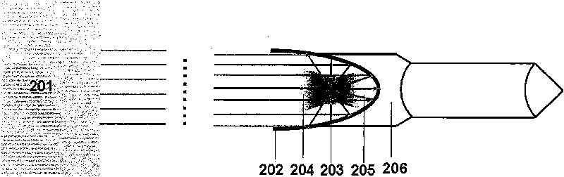
[0028] image 3 is a schematic diagram of a laser propulsion device according to one embodiment of the present invention employing solid particle or cluster propellants. Different from the laser propulsion device in Embodiment 1, this embodiment uses solid particle or cluster propellant 303 instead of film propellant 103 , and uses nozzle 307 instead of belt conveyor 107 . Such as image 3 As shown, solid particle or cluster propellant 303 is ejected using nozzle 307 . During the working process of the device, due to the low surface density of solid particles or clusters and the high absorption efficiency of laser light, no critical density surface will be formed, and the laser ablation will not be blocked, and the distance between particles is relatively large, so it will not be caused by Thermal diffusion results in energy loss that essentially converts the solid particle or cluster propellant into a plasma, resulting in a higher specific impulse. In addition, the injecti...

Embodiment 3

[0030] Figure 5 is a schematic diagram of a laser propulsion device according to an embodiment of the present invention using a disc conveyor. Different from the laser propulsion device of Embodiment 1, this embodiment uses a lightweight foam material propellant (not shown) instead of the film propellant 103 , and uses a disc conveyor 501 instead of the belt conveyor 107 . The thickness of the lightweight foam propellant is less than or equal to the ablation depth of the laser. During the working process of the device, the disc conveyor 501 continuously delivers the lightweight foam propellant to the opening, and when the laser irradiates the propellant, it is basically completely ablated and transformed into plasma to propel the lightship. In the present invention, the lightweight foam propellant may be a commercially available foam whose main component is polystyrene. In addition, the lightweight foam propellant can be either a pan conveyor or a figure 1 A belt conveyor ...


PUM


Abstract

The invention discloses a laser propulsion device. The device comprises a laser device, a propellant feeding device, laser focusing equipment and a combustion chamber, wherein the laser device is used for generating laser; the laser focusing equipment is used for focusing the laser on a propellant; the propellant feeding device is used for providing the propellant and the propellant within a laser irradiation area is mainly converted into plasma; and the combustion chamber is used for transmitting the energy of the plasma to a lightcraft. The laser propulsion device can avoid heat conduction generated when the laser ablates a solid propellant and propellant loss caused by material sputtering, thereby increasing the actual specific impulse of laser propulsion.

Description

technical field [0001] The invention relates to the field of laser propulsion, in particular to a laser propulsion device. Background technique [0002] Laser propulsion is a new concept propulsion technology proposed by American scholar Kantrowitz in the 1970s. Its basic principle is to use a strong laser to irradiate and ablate the propellant at the tail of the rocket, generating plasma far beyond the combustion temperature, high temperature and high pressure The laser plasma is ejected at extremely high speeds, creating a powerful recoil that propels the rocket forward. In this field, the specific impulse (the mass of the propellant consumed to generate the unit impulse, in engineering, for the sake of convenience, the denominator of the international unit of specific impulse N s / kg is often multiplied by the acceleration of gravity g, so the specific impulse The unit is usually seconds) is the most important technical index to measure the fuel utilization rate of laser ...

Claims


Application Information

Patent Timeline
Patent Type & Authority Applications(China)
IPC IPC(8): F02K9/95F02K9/08
Inventor 鲁欣张翼张杰
Owner INST OF PHYSICS - CHINESE ACAD OF SCI
Why Eureka
Try Eureka