Eureka AIR delivers breakthrough ideas for toughest innovation challenges, trusted by R&D personnel around the world.

Dry vertical shaft storage system for spent fuel of nuclear power station and storage method thereof

A spent fuel and nuclear power plant technology, applied to the spent fuel storage system of pebble bed high-temperature gas-cooled reactor nuclear power plant and its storage field, to prevent the impact of external events, reduce the amount of three wastes, and reduce the effect of initial investment

Active Publication Date: 2010-06-16
CHINERGY CO LTD
View PDF0 Cites 33 Cited by
  • Summary
  • Abstract
  • Description
  • Claims
  • Application Information

AI Technical Summary

Problems solved by technology

However, since a large amount of spent fuel produced by nuclear power plants has not been processed, and the pools stored in the reactor have been filled, in order to meet the storage problem of a large amount of spent fuel, a dry storage container technology has been developed. The dry storage container consists of two parts: inner A metal bare tank and an outer concrete shielding tank. A storage grid is set inside the bare tank, and the spent fuel is placed in the storage grid. After the bare tank is sealed, it is placed in a concrete shielding tank and then transported to the spent fuel near the power plant. Intermediate storage at fuel storage sites

Method used


Image

  • Dry vertical shaft storage system for spent fuel of nuclear power station and storage method thereof
  • Dry vertical shaft storage system for spent fuel of nuclear power station and storage method thereof
  • Dry vertical shaft storage system for spent fuel of nuclear power station and storage method thereof

Examples


Embodiment Construction

[0050] The specific implementation manners of the present invention will be further described in detail below in conjunction with the accompanying drawings and embodiments. The following examples are used to illustrate the present invention, but are not intended to limit the scope of the present invention.

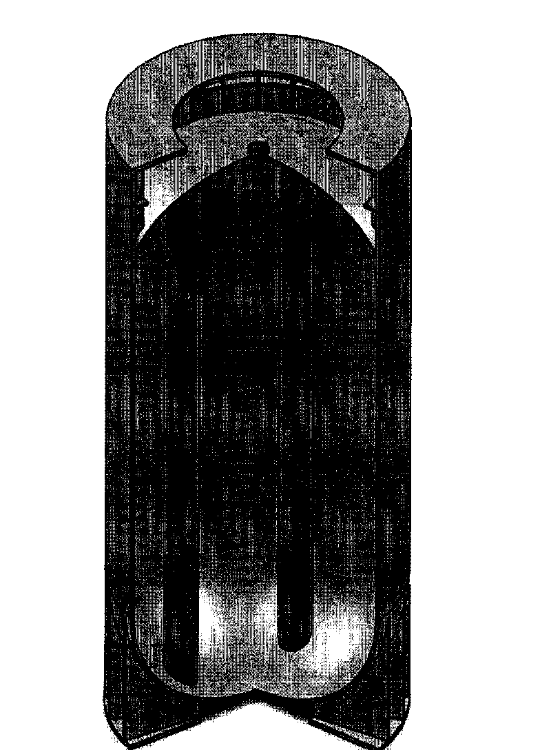
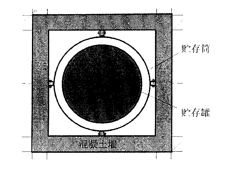
[0051] figure 1 It is a schematic diagram of a spent fuel storage tank of a dry shaft storage system for nuclear power plant spent fuel according to the present invention, and the spent fuel is stored in the spent fuel storage tank. The spent fuel storage tank is a thin-walled bare tank. The height of the tank is about 4m, and the outer diameter is about 1.8m. It can be put into the shielded transfer container of spent fuel as a whole to facilitate the transfer of spent fuel. The top of the spent fuel storage tank is equipped with a hoisting port, through which the hoisting of the spent fuel storage tank can be remotely controlled and monitored in real time, and the hois...


PUM

PropertyMeasurementUnit
Heightaaaaaaaaaa
Outer diameteraaaaaaaaaa

Abstract

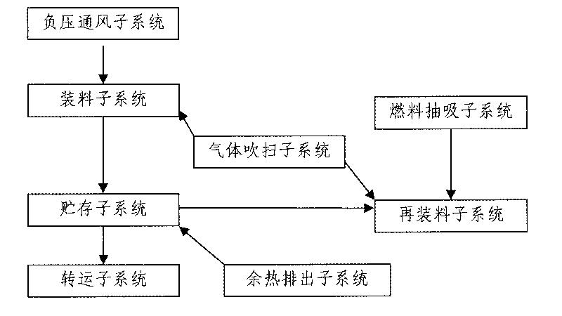
The method provides a dry vertical shaft storage system for spent fuel of a nuclear power station and a storage method thereof. The system comprises a loading subsystem, a storage subsystem, a reloading subsystem, a transferring subsystem, a residual heat discharge subsystem, a negative pressure ventilation subsystem, a fuel suction subsystem and an air blowing subsystem. The system saves a water-cooling system and a water purification system on the basis of the water storage method; the storage vertical shaft is arranged underground, so that the influence of an external event can be effectively prevented, such as airplane crash; when the spent fuel needs to be transferred, a spent fuel storage tank can be taken out of a storage depot, and then directly loaded in a spent fuel shielding transport cask through lifting equipment so as to be conveniently transported; a plant and structural equipment are not polluted by radioactive materials, so the spent fuel storage depot can be normally disassembled and retired after the spent fuel storage tank is transferred; radioactive decontamination is not needed and the spent fuel storage depot can be conveniently retired; and the storage tank can be processed in different phases to reduce initial cost according to the operation of the power station.

Description

technical field [0001] The invention relates to a dry shaft storage system for nuclear power plant spent fuel and its storage method, in particular to a pebble bed type high temperature gas-cooled reactor nuclear power plant spent fuel storage system and its storage method. Background technique [0002] During the operation of nuclear power plants, spent fuel will be produced. A nuclear power unit with a power of one million kilowatts will produce tens of tons of spent fuel every year. According to my country's nuclear power development plan, after 2020, the amount of spent fuel produced in my country will exceed 1,000 tons per year, and the storage and treatment of spent fuel will become an important issue that the country needs to consider. [0003] According to the policy of a national nuclear energy strategy, different disposal measures can be adopted for the spent fuel discharged after the operation of the nuclear power plant reactor. Separation and recycling, solidifi...

Claims


Application Information

Patent Timeline
IPC IPC(8): G21C19/06G21F5/008
CPCY02E30/30
Inventor 张作义王金华
Owner CHINERGY CO LTD
Why Eureka
Eureka Blog
Learn More