Single-negative material ultra-slow waveguide-based miniaturized patch antenna

A patch antenna and single-negative technology, applied in the direction of antennas, electrical components, etc., can solve problems such as low radiation efficiency and pattern distortion, and achieve a simple feeding method, no pattern distortion, and easy large-scale processing and production Effect

Inactive Publication Date: 2010-06-16
ZHEJIANG UNIV
View PDF3 Cites 2 Cited by
  • Summary
  • Abstract
  • Description
  • Claims
  • Application Information

AI Technical Summary

Problems solved by technology

[0004] The purpose of the present invention is to overcome the deficiencies such as low radiation efficiency and pattern distortion common in the existing patch antenna miniaturization te

Method used


Image

  • Single-negative material ultra-slow waveguide-based miniaturized patch antenna
  • Single-negative material ultra-slow waveguide-based miniaturized patch antenna
  • Single-negative material ultra-slow waveguide-based miniaturized patch antenna

Examples


Embodiment Construction

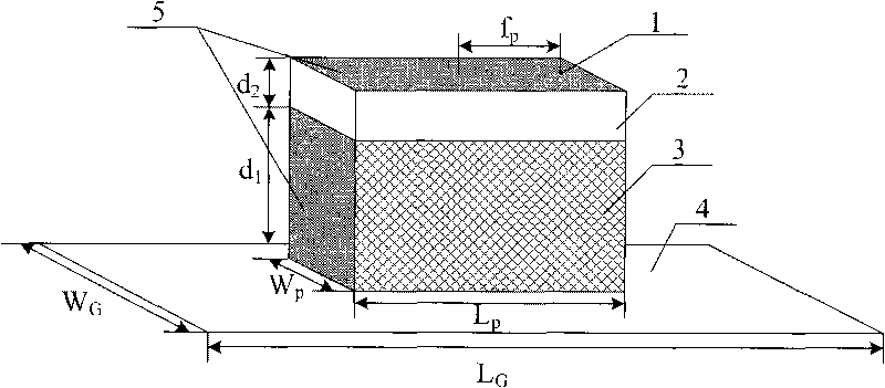
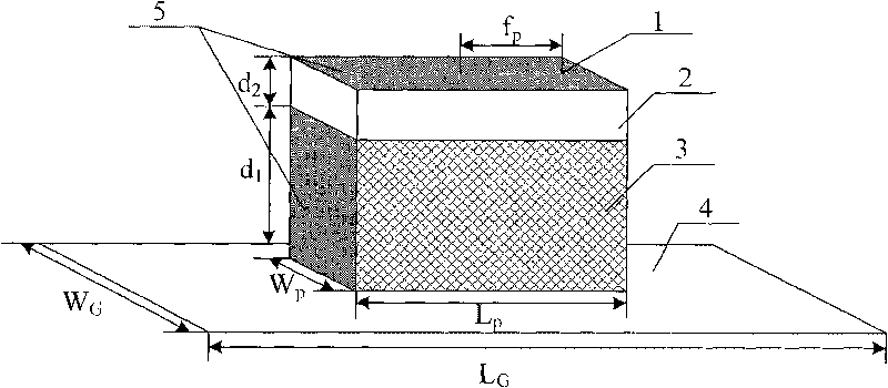
[0013] Such as figure 1 As shown, the antenna can be operated at any working frequency, and the working frequency can be selected according to user requirements. For the convenience of description, this embodiment selects λ=2.3 GHz as the working frequency of the antenna for illustration. The dielectric substrate of the antenna is composed of two layers, namely a negative dielectric constant dielectric layer 3 and a common dielectric layer 2 . The length L of both P Both are λ / 7.7, width W P Both are λ / 6.5, the height d of the negative dielectric constant dielectric layer 3 1 is λ / 26, the height d of ordinary dielectric layer 2 2 λ / 144.9, dielectric constant ε 1 = -4.5, ε 2 =1, the magnetic permeability is 1. The upper surface of the ordinary dielectric layer 2 is coated with an ideal electric conductor layer 5 . The negative dielectric constant dielectric layer 3 is located on the metal ground plane layer 4, and the length L of the metal ground plane layer 4 G and wi...


PUM


Abstract

The invention relates to a single-negative material ultra-slow waveguide-based miniaturized patch antenna. The traditional patch antenna is large in size and poor in radiation efficiency and directionality. The miniaturized patch antenna comprises a negative dielectric constant dielectric layer, a common dielectric layer, a metal horizontal plane layer and a coaxial feed probe, wherein the negative dielectric constant dielectric layer is arranged between the common dielectric layer and the metal horizontal plane layer; the upper surface of the common dielectric layer is coated with an ideal electric conductor; the area of the metal horizontal plane layer is greater than that of the bottom surface of the negative dielectric constant dielectric layer; and the coaxial feed probe penetrates the negative dielectric constant dielectric layer, the common dielectric layer and the metal horizontal plane layer and is vertical to the negative dielectric constant dielectric layer, the common dielectric layer and the metal horizontal plane layer. The antenna has the advantages of very small size, simple feed method, convenient large-scale manufacture and low cost.

Description

technical field [0001] The invention belongs to the antenna field of a communication system, and relates to a miniaturized patch antenna based on a single negative material ultra-slow wave guide. Background technique [0002] As a new type of antenna, the microstrip patch antenna has been widely studied and applied in the field of modern defense and civil communication. It has many advantages such as low profile, small size, light weight, low cost, easy conformal design, and easy integration with active devices and circuits into a single module. [0003] However, because the resonant length of the traditional patch antenna requires half the wavelength of the waveguide, its size has been difficult to meet the requirements of future military and civilian communications for highly miniaturized antennas. Popular chip antenna miniaturization technologies include the use of high dielectric constant substrates, loading short-circuit pins or short-circuit surfaces, slotting on the ...

Claims


Application Information

Patent Timeline
IPC IPC(8): H01Q13/08
Inventor 熊江何赛灵
Owner ZHEJIANG UNIV
Why Eureka
Try Eureka