Rotary compressor

A technology of rotary compressors and compression mechanisms, which is applied to rotary piston machines, rotary piston pumps, mechanical equipment, etc., and can solve the problems of reducing the amount of refrigerant enclosed and performance degradation

Active Publication Date: 2010-06-16
MITSUBISHI ELECTRIC CORP
View PDF2 Cites 19 Cited by
  • Summary
  • Abstract
  • Description
  • Claims
  • Application Information

AI Technical Summary

Problems solved by technology

In this proposal, since there is no means for adjusting the amount of oil stored on the side of the high-pressure oil separator, if the amount of oil on the high-pressure side increases excessively, the amount of refrigerant dissolved in the lubricating oil will increase. Since a large amount of refrigerant is specifie

Method used


Image

  • Rotary compressor
  • Rotary compressor
  • Rotary compressor

Examples


Embodiment approach 1

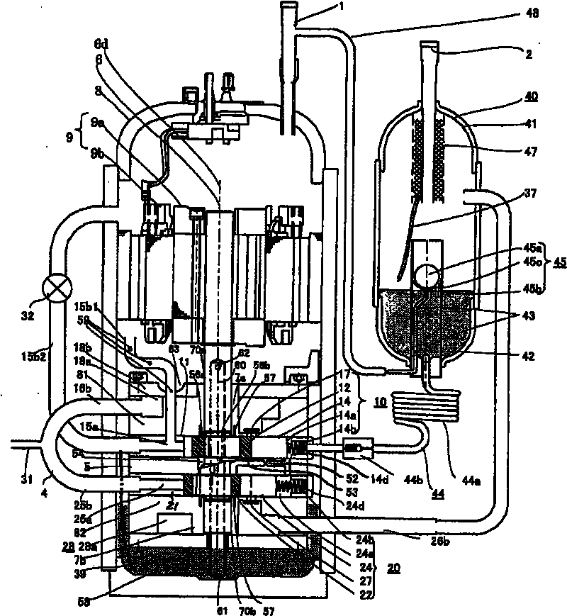
[0030] figure 2 It is an assembly drawing showing the overall structure of the low-pressure shell-type two-stage rotary compressor according to Embodiment 1 of the present invention. The rotary compressor of the present invention includes a hermetic container 8, a motor 9 installed in the hermetic container 8, a crankshaft 6 driven by the motor 9, a long-axis side bearing 7a and a short-axis side bearing 7b supporting both ends of the crankshaft 6, first and The second compression mechanisms 10 and 20 are equipped with an oil separation element 40 outside the sealed container 8 .

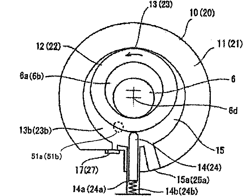
[0031] image 3 yes means figure 2 A cross-sectional view of the structure of the shown low-stage compression mechanism (first compression mechanism). The structure of the high-stage compression mechanism (second compression mechanism) is also the same as that of the low-stage side, and is denoted by reference symbols in parentheses. As the crankshaft 6 rotates around the axis 6d, the cranksha...

Embodiment approach 2

[0056] Figure 8 It is an assembly diagram showing the overall structure of a low-pressure shell-type two-stage rotary compressor according to the second embodiment. The rotary compressor is Figure 1 to Figure 7 The rotary compressor of Embodiment 1 shown is structurally different in that the low-stage discharge muffler 18, the low-stage discharge valve 17, and the intermediate connecting portion are provided in the intermediate plate 5, and the oil separator 90 is provided in the The internal space 28b of the high-level discharge muffler container 28 in the airtight container 8 also serves as the structure of the high-level discharge muffler, so the oil supply path of the high-pressure lubricating oil separated by the oil separator 90 is different. Other configurations are the same as those in Embodiment 1, and therefore description thereof will be omitted.

[0057] That is, the intermediate plate 5 is composed of upper and lower two laminated plates, that is, a first inte...

Embodiment approach 3

[0066] Figure 9 It is an assembly drawing showing the overall structure of the low-pressure shell-type single-stage rotary compressor according to the second embodiment. The difference in structure from the rotary compressor of Embodiment 2 is that it is a single-stage rotary compressor composed of one compression mechanism, and the bottom shell of the hermetic container 8 is configured to double as a high-pressure container 41 for an oil separator and The structure of the discharge muffler 18 is such that, in the container 41 , a swirling flow generation rotating body 64 functioning as an oil separation member is provided at the lower end of the crankshaft 6 , and an oil pump rotating body 61 is attached as an oil supply member. Other configurations are the same as those in Embodiment 2, and description thereof will be omitted. Here, the single-stage compression mechanism itself is associated with Figure 3-5 The compression mechanism of Embodiment 1 shown is the same, and...


PUM


Abstract

A natural refrigerant low-pressure shell-type rotary compressor in which the amount of oil contained on the high-pressure side is reduced with sufficient lubrication and sealing performance at a sliding section secured. The compressor has a rotary refrigerant compression mechanism provided in a low-pressure enclosed container and having vanes, an oil separation element for separating lubricating oil from the refrigerant, and an oil supply passage for supplying the separated lubricating oil to a vane back pressure chamber of the compression mechanism, a crankshaft, a bearing, a cylinder, a piston, and oil supply spaces between the vanes. Vane skip is suppressed, and efficient lubrication and high sealing performance at the sliding section and a reduction in the amount of the oil contained on the high-pressure side are achieved at the same time. The compressor is highly reliable, is of low cost, has high performance, and uses a reduced amount of refrigerant.

Description

technical field [0001] The present invention relates to a rotary compressor, in particular to a natural refrigerant low pressure shell type rotary compressor. Background technique [0002] Since the rotary compressor can be downsized and has a simple structure, it is widely used in refrigerators, air conditioners, heat pump water heaters, and the like (see Non-Patent Document 1). In recent years, from the viewpoint of preventing global warming, natural refrigerants with zero ozone depletion coefficient and low global warming coefficient have been focused on as new refrigerants to replace CFCs, especially non-toxic and non-flammable carbon dioxide ( CO 2 ) refrigerants and hydrocarbon (HC) refrigerants that are flammable but have excellent refrigerant properties. In Table 1, as a comparison table, Freon refrigerants (R22, R410A) and HC refrigerants (isobutane, propane), CO 2 The operating conditions of the rotary compressor of the refrigerant are expressed from the Ashrae-...

Claims


Application Information

Patent Timeline
IPC IPC(8): F04C18/356F04C23/00F04C29/02
CPCF04C29/026F04C18/344F04C23/008F04C18/356F01C21/0872F04C23/001
Inventor 横山哲英幸田利秀关屋慎佐佐木圭前山英明
Owner MITSUBISHI ELECTRIC CORP
Why Eureka
Try Eureka