Grinding material vibration porous deburring process

A deburring and vibrating grinding technology, which is applied in the direction of manufacturing tools, ultra-finishing machines, metal processing equipment, etc., can solve problems such as high labor intensity and difficulty in meeting processing requirements

Inactive Publication Date: 2010-06-23
SHENYANG LIMING AERO-ENGINE GROUP CORPORATION
View PDF0 Cites 11 Cited by
  • Summary
  • Abstract
  • Description
  • Claims
  • Application Information

AI Technical Summary

Problems solved by technology

However, in actual production, when deburring some key spare parts, manual methods are often used, which is not only labor-intensive, but also difficult to meet processing requirements.

Method used


Image

  • Grinding material vibration porous deburring process
  • Grinding material vibration porous deburring process
  • Grinding material vibration porous deburring process

Examples


Embodiment 1

[0024] 1 Vibration deburring test of spray rod tiny holes

[0025] (1) Vibrating magnetic abrasive grinding method

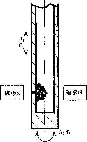
[0026] Process flow: such as figure 1 As shown, the magnet adopts a strong permanent magnet or an electromagnet, and the abrasive particles in the magnetic field act on the burr surface with a certain pressure; when the magnet or the workpiece vibrates with a certain amplitude and frequency, there is a controllable relative motion between the abrasive particles and the workpiece , thus generating cutting force for deburring.

[0027] (2) Vibrating liquid abrasive grinding method

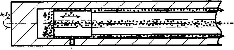
[0028] Process flow: such as figure 2 As shown, the method uses a vibrating device to excite the grinding rod with adjustable amplitude and frequency. The grinding rod drives the liquid abrasive to generate cutting force for removing micropore burrs, and the liquid abrasive is injected circularly by an abrasive pump.

Embodiment 2

[0030] Vibration nozzle deburring test:

[0031] According to the shape of the nozzle bore burr, 3 to 4 processes are used to complete the deburring.

[0032] (1) For large nozzle workpieces

[0033] The process flow is as follows:

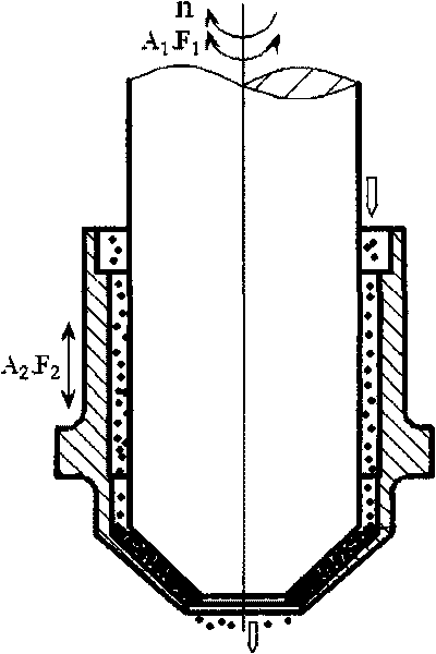
[0034] The first step process: remove the burrs turned outward at the entrance. Such as image 3 As shown, the inner tapered surface of the workpiece is ground with a grinding tool with an outer tapered surface to remove burrs. The abrasive tool rotates at a speed n while making a certain amplitude A 1 , frequency F 1 The torsional vibration accelerates the grinding effect; the amplitude of the workpiece is A 2 , frequency F 2 The axial vibration can make the circulating abrasive fully enter between the abrasive tool and the surface to be ground; the grinding pressure between the abrasive tool and the workpiece is P.

[0035] The second step of the process: remove the burrs turned outward at the exit. Such as Figure 4 As shown, the oute...

Embodiment 3

[0041] Vibration deburring test results of spray rod tiny holes

[0042] (1) Vibrating magnetic abrasive grinding method

[0043] The test parameters are shown in Table 1:

[0044] Table 1 Vibration Magnetic Abrasive Grinding Test Parameters

[0045] Torsional Vibration Parameters

[0046] (2) Vibrating liquid abrasive grinding method

[0047] The actual test device is used as the principle test equipment

[0048] The test parameters are shown in Table 2:

[0049] Table 2 Vibration liquid abrasive grinding method test parameters

[0050] Torsional Vibration Parameters

[0051] Figure 7It is the comparison curve of vibratory grinding and ordinary grinding spray rod: It can be seen from the test results that the two experimental schemes of vibrating magnetic abrasive grinding and vibrating liquid abrasive grinding can completely remove the burrs of the spray rod micropores, while maintaining the uniformity of the pore diameter. Sharp edges, and vibrati...


PUM


Abstract

The invention relates to a grinding material vibration porous deburring process. Vibration energy is attached to a grinding tool or a ground workpiece to vibrate the grinding tool or the workpiece at a certain frequency and amplitude in a grinding direction, and a dissociative grinding material is put on the surface of the roughly processed workpiece to complete deburring or finishing processing. Cured vibration parameters include: torsional vibration parameters: A2=1mm and F2=10Hz; and axial vibration parameters: A1=0, F1=0 and a magnetic grinding material. Liquid grinding material vibration grinding test parameters: torsional vibration parameters: A2=0 and F2=0; axial vibration parameters: A1=0.4mm and F1=20Hz; and a liquid grinding material. The invention has the advantages that the grinding material vibration porous deburring process is an improved grinding method for vibrating the grinding tool or the workpiece in the traditional grinding processing, has simple operation, significant effect, high efficiency and low cost, belongs to ultra fine grinding, has minimal impact on the size precision of the inner conical surface and the outer conical surface of a nozzle and has high processing efficiency.

Description

technical field [0001] The invention relates to the technical field of mechanical design and machining, and in particular provides a vibrating abrasive micropore deburring process. Background technique [0002] Machining can hardly prevent the occurrence of burrs; the existence of burrs will seriously affect the assembly accuracy and performance of the product. Therefore, during the manufacturing process of the parts, the burrs of the parts must be removed; especially in the manufacture of some key parts, the existence of burrs cannot be allowed for precision parts that are often used in special occasions. In actual production, when deburring some key spare parts, manual methods are often used, which is not only labor-intensive, but also difficult to meet processing requirements. [0003] At present, it has developed from simple cleaning processes such as rust removal, sand removal, and scale removal to high-level deburring processes such as high temperature, electrolysis, ...

Claims


Application Information

Patent Timeline
IPC IPC(8): B24B1/04B24B35/00
Inventor 杨金发孙安有张德远于在梅庞继有叶洪涛
Owner SHENYANG LIMING AERO-ENGINE GROUP CORPORATION
Why Eureka
Try Eureka