H-shaped two-dimensional ultraprecise worktable structure

An ultra-precise, workbench technology, applied in the field of ultra-precise positioning technology and devices, can solve the problems of limited guiding accuracy, Y-axis slider or guide rail deformation, easy deformation, etc., to achieve the elimination of error superposition, good accuracy retention, and sliding The effect of high block stiffness

Inactive Publication Date: 2010-06-23
BEIJING UNIV OF TECH
View PDF0 Cites 6 Cited by
  • Summary
  • Abstract
  • Description
  • Claims
  • Application Information

AI Technical Summary

Problems solved by technology

This non-closed slider structure has poor rigidity and is easy to deform, which limits the guiding accuracy
based on Figure 3a and Figure 3b For the H-type two-dimensional worktable based on the guiding principle, the deformation of the Y-axis slider limits the angular accuracy between the X-axis guide rail and the Y-axis guide rail, and also limits the positioning accuracy of the H-type two-dimensional workbench.
[0007] Based on the above principles, the existing H-type two-dimensional workbench is essentially a superimposed structure. The X-axis positioning accuracy is not only affected by factors such as the X-axis guide rail guidance accuracy, slider stiffness, and guide rail accuracy retention, but also by the Y-axis positioning. The influence of precision; while the weight of the slider on the X-axis and the weight of the load are borne by the Y-axis slider, resulting in deformation of the Y-axis slider or guide rail, which affects the positioning accuracy of the Y-axis; the positioning accuracy of the X-axis and the Y-axis affect each other, Limits the positioning accuracy of the 2D workbench

Method used


Image

  • H-shaped two-dimensional ultraprecise worktable structure
  • H-shaped two-dimensional ultraprecise worktable structure
  • H-shaped two-dimensional ultraprecise worktable structure

Examples


Embodiment Construction

[0034] Attached below Figure 4a and Figure 4b The present invention is described further:

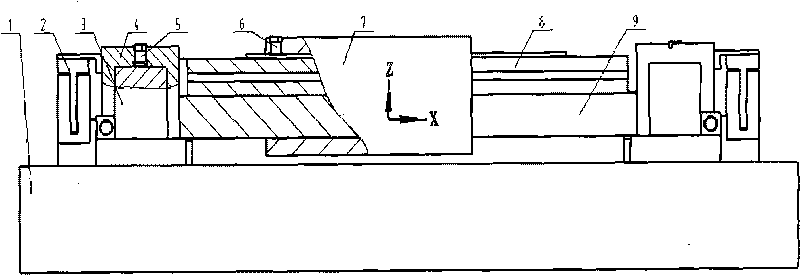
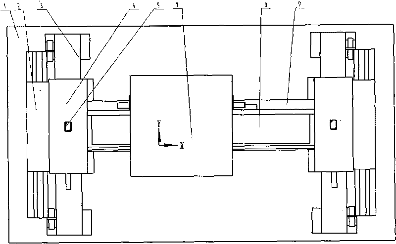
[0035] Structure description: The X-axis slider 22 and the Y-axis slider 27 with a vacuum chamber are air-floated on the base 17. When compressed gas is passed, the X-axis slider 22 and the upper surface of the base 17 form a static pressure air float State, the Y-axis slider 27 and the upper surface of the base 17 form a static pressure air floatation state; the two ends of the X-axis guide rail 25 are rigidly connected with the Y-axis slider 27; the Y-axis guide rail 21 is fixed on the base 17 through the guide rail pad 28 ; The X-axis slider 22 is encircled on the X-axis guide rail 25; the Y-axis slider 27 is encircled on the Y-axis guide rail 21; The mover of the X-axis drive part 26 is connected with the X-axis slider 22; the stator of the Y-axis drive part 18 (a linear motor in this embodiment) is rigidly connected with the base 17, and the mover of the Y-axis drive part 18 is...


PUM


Abstract

The invention relates to an H-shaped ultraprecise worktable structure, belonging to the fields of precise measurement, ultraprecise machining, minitype machines, nanometer, and the like. An X-axis slide block is encircled on an X-axis guide rail, the two ends of the X-axis guide rail are fixed on two Y-axis slide blocks which are encircled on a Y-axis guide rail, and the Y-axis guide rail is fixed on a base through a guide rail pad. The H-shaped ultraprecise worktable structure is characterized in that the X-axis slide block and the Y-axis slide blocks are designed as symmetrical and closed structures, and fixed compressed gas film clearances are retained among the slide blocks and the upper surface of the base, a clearance between the upper surface of the X-axis guide rail and the upper surface in the X-axis slide block is no less than the deformation of the X-axis guide rail caused by the weight of the X-axis guide rail, a clearance between the lower surface of the X-axis guide rail and the lower surface in the X-axis slide block is no less than the deformation of the X-axis guide rail caused by the weight of the X-axis guide rail, and the design of the Y-axis guide rail is the same as that of the X-axis guide rail. By adopting the structure, the guiding precise of the guide rails and the stability of the worktable structure are improved, and the positioning precision of the X-axis and the Y-axis are not influenced by each other, thereby the effect of error superposition is avoided. In addition, the system has high rigidity and good precision retaining ability.

Description

technical field [0001] The invention relates to ultra-precise positioning technology and devices, and belongs to the technical fields of precision measurement, ultra-precision machining, micromachines and nanotechnology. Background technique [0002] Ultra-precision tables are the basis for precision measurement, ultra-precision machining, micro-assembly, semiconductor lithography and nanotechnology. The positioning accuracy of the two-dimensional precision table is not only related to the accuracy of the guide rail, but also related to the structural relationship in two dimensions. The H-type two-dimensional precision table is widely used because of its compact structure and high positioning accuracy. The structure principle of the existing H-shaped two-dimensional precision workbench is as follows: Figure 1a and Figure 1b shown. Figure 1a and Figure 1b Middle: 1 is the base, 2 is the Y-axis driving device, 3 is the Y-axis guide rail, 4 is the Y-axis slider, 5 is the...

Claims


Application Information

Patent Timeline
Patent Type & Authority Applications(China)
IPC IPC(8): B81C3/00B82B3/00G01B21/02
Inventor 石照耀张斌林家春
Owner BEIJING UNIV OF TECH
Why Eureka
Try Eureka