
Blowing drying device after underwater pressure test of welded pipe

A drying device and welded pipe technology, applied in the direction of progressive dryers, drying solid materials, and drying solid materials without heating, etc., can solve the problems of non-drying, rubbing off the surface of metal pipes, corrosion spots of stainless steel, etc., and save manpower and material resources , avoid water stains and rust, and dry completely

Active Publication Date: 2010-06-23
上海华钢不锈钢有限公司
View PDF0 Cites 3 Cited by
  • Summary
  • Abstract
  • Description
  • Claims
  • Application Information

AI Technical Summary

Problems solved by technology

[0002] In the prior art, after the underwater airtightness test of the stainless steel welded pipe, it is required to dry the moisture on the surface of the stainless steel welded pipe. Usually, it is directly dried manually with a rag, but it is easy to wipe off the spray on the surface of the metal pipe if it is directly dried with a rag. code erased
[0003] That is to say, the traditional stainless steel welded pipe drying process cannot effectively and completely dry the outer surface, the work efficiency is low, and it will also affect the continuity of the production line.
If the surface of the stainless steel pipe stained with moisture is not dried in time and completely, the surface of the stainless steel welded pipe will be prone to water rust and water stains, which will affect the apparent quality of the product.
The trivalent iron oxide in the scale will also cause corrosion points to stainless steel, which is not allowed for high-demand stainless steel products

Method used


Image

  • Blowing drying device after underwater pressure test of welded pipe
  • Blowing drying device after underwater pressure test of welded pipe
  • Blowing drying device after underwater pressure test of welded pipe

Examples


Embodiment Construction

[0011] Below in conjunction with accompanying drawing and specific embodiment the present invention is described in further detail:

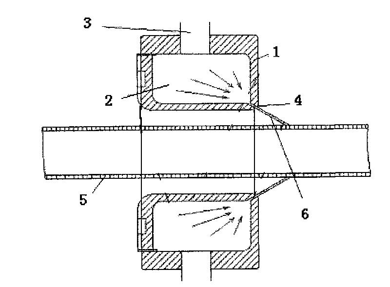
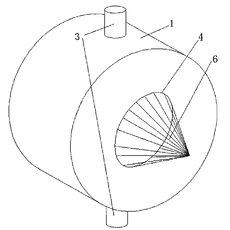
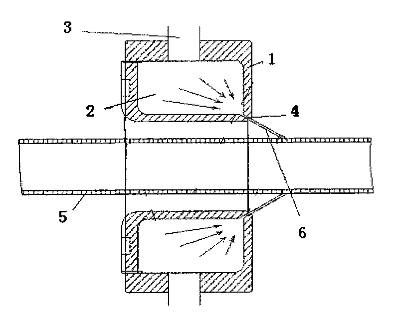
[0012] Depend on figure 1 , figure 2 It can be seen that the present invention includes: a cylindrical passage 1 through which the stainless steel welded pipe 5 can pass; at least one air inlet 3 is arranged outside the cylindrical passage 1, and there is an annular air cavity 2 inside the cylindrical passage 1; The annular air chamber 2 is connected to the air inlet 3; there is a blowing gap 4 at a corner of the annular air chamber 2, near the axis of the cylindrical channel 1;

[0013] The blowing slit 4 is at an angle of 45° to the axial direction of the annular cavity.

[0014] In the present invention, when the stainless steel welded pipe after the hydrostatic test passes through the conical air curtain 6 ejected from the annular gap of the cylindrical channel, the moisture on the surface of the steel pipe can be quickly blown away, so t...


PUM


Abstract

The invention relates to a blowing drying device after underwater pressure test of a welded pipe, comprising a cylindrical channel (1) leading a stainless steel welded pipe (5) to penetrate through, at least more than one air inlet (3) is arranged at the outer side of the cylindrical channel (1), an annular air cavity (2) is arranged at the inner side of the cylindrical channel (1), the annular air cavity (2) is connected with the air inlet (3), and a blowing gap (4) is arranged at a corner of the annular air cavity (2) and close to the axis of the cylindrical channel (1). The blowing drying device has the benefits that the production of the stainless steel pipes is continuous, the drying is complete, fast and high efficient, the problems of water stain and scale and probable corrosion pits on the surface of the stainless steel pipe and water residue in product packaging are avoided, and a large number of manpower and material resources are saved as well.

Description

technical field [0001] The invention relates to a drying device, in particular to a blowing drying device for a welded pipe after underwater pressure test. Background technique [0002] In the prior art, after the underwater airtightness test of the stainless steel welded pipe, it is required to dry the moisture on the surface of the stainless steel welded pipe. Usually, it is directly dried manually with a rag, but it is easy to wipe off the spray on the surface of the metal pipe if it is directly dried with a rag. The code is wiped off. [0003] That is to say, the traditional stainless steel welded pipe drying process cannot effectively and completely dry the outer surface, the work efficiency is low, and it will also affect the continuity of the production line. If the surface of the stainless steel pipe stained with moisture is not dried in time and incompletely, the surface of the stainless steel welded pipe will be prone to water rust and water stains, which will aff...

Claims


Application Information

Patent Timeline
Patent Type & Authority Applications(China)
IPC IPC(8): F26B13/02F26B5/00
Inventor 王爵光
Owner 上海华钢不锈钢有限公司
Learn More