
Lower conducting dome of inorganic electroluminescent display and production method thereof

A manufacturing method and bottom electrode technology, applied in the direction of electroluminescent light source, electric light source, light source, etc., can solve the problems of poor conduction, low temperature resistance of the bottom electrode, etc., and achieve low cost, high withstand voltage, and good reliability Effect

Inactive Publication Date: 2010-06-23
INESA ELECTRON
View PDF0 Cites 0 Cited by
  • Summary
  • Abstract
  • Description
  • Claims
  • Application Information

AI Technical Summary

Problems solved by technology

[0004] The present invention provides a bottom electrode in an inorganic electroluminescent display and a manufacturing method thereof. The bottom electrode in the inorganic electroluminescent display and a manufacturing method thereof need to solve the problem of top emission structure inorganic EL in the prior art. The bottom electrode is not resistant to high temperature and has poor electrical conductivity.

Method used


Image

  • Lower conducting dome of inorganic electroluminescent display and production method thereof
  • Lower conducting dome of inorganic electroluminescent display and production method thereof
  • Lower conducting dome of inorganic electroluminescent display and production method thereof

Examples


Embodiment 1

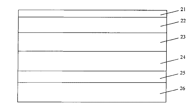
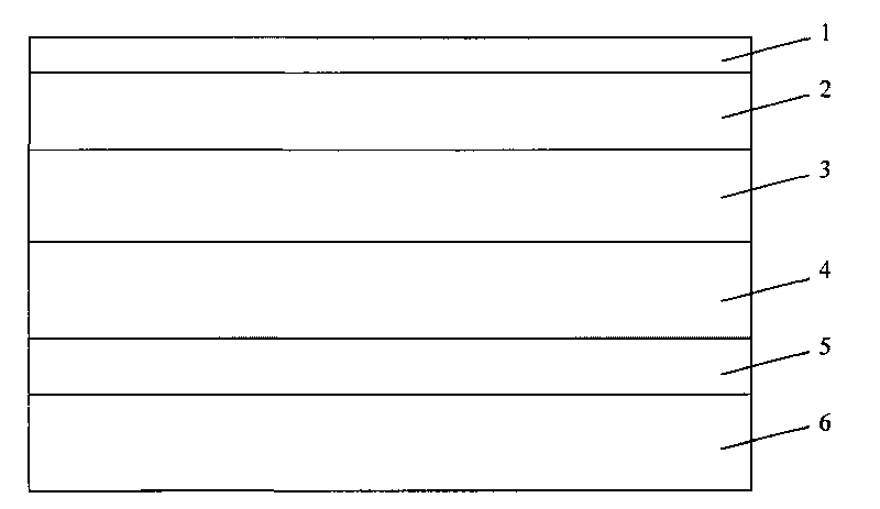
[0017] Such as figure 2 As shown, an inorganic electroluminescence display comprises a layer of glass 6, a layer of bottom electrode 5 is arranged on the glass 6, and a layer of lower dielectric layer 4 is arranged on the top of the bottom electrode 5, and the lower dielectric layer 4 is arranged on the bottom electrode 5. A light-emitting layer 3 is arranged on the upper part of the medium layer 4 , an upper dielectric layer 2 is arranged on the upper part of the light-emitting layer 3 , and an upper electrode 1 is arranged on the upper part of the upper dielectric layer 2 .

[0018] Further, the material of the bottom electrode 5 is Ti-Au composite film.

[0019] Further, the upper electrode 1 is ITO.

[0020] Further, the upper dielectric layer 2 is selected from Al 2 o 3 , or Ta 2 o 5 .

[0021] Further, the light-emitting layer 3 is selected from a mixture of ZnO and Mn.

[0022] Further, the material of the lower dielectric layer 4 is BaSrTO 3 .

Embodiment 2

[0024] Such as figure 2 As shown, the present invention also provides a method for making the bottom electrode of an inorganic electroluminescent display. First, the TFT glass 6 is cleaned and dried, and the glass substrate 6 is placed in an electron beam evaporation device, and the vacuum is evacuated to 1.5×10 -3 Pa-3.0×10 -3 The air pressure of Pa, glass substrate 6 temperature is heated to 130-180 ℃, and evaporation rate is Using 99.9% pure Ti target material, 45- Thick Ti film, then turn the Au target to the evaporation position, the purity of Au is 99.9%, and also evaporate 140- Thick Au film, after the amplified gas is taken out from the vacuum chamber, the bottom electrode 5 of the device is completed.

[0025] Further, the glass substrate 6, the bottom electrode 5, the lower dielectric layer 4, and the luminescent layer 3 are heated together by means of electric heating wire heating.


PUM


Abstract

The invention provides a lower conducting dome of an inorganic electroluminescent display, wherein the material of the lower conducting dome is Ti-Au composite film. The invention further provides a production method of the lower conducting dome of the inorganic electroluminescent display, which comprises the steps of first cleaning and drying TFT glass, putting a glass substrate in electron beam evaporation equipment, vacuumizing to achieve the air pressure of 1.5*10<-3>Pa-3.0*10<-3>Pa, heating the substrate to reach the temperature of 130-180 DEG C so that the evaporation rate reaches 1.8-2.2 A / s, adopting Ti target material, plating a thick Ti film by using an electron beam evaporation method, and then evaporating a thick Au film. The invention is applicable to AC drive mode work, compared with the prior art, the invention has the characteristics of high pressure resistance, small electric leakage, good reliability, large glow brightness, long service life, low cost and the like, is applicable for flat panel displays with a large area, and simultaneously has the characteristics that the lower conducting dome has simple production technology and is suitable for mass production.

Description

Technical field: [0001] The invention belongs to the technical field of flat panel display, and in particular relates to an inorganic electroluminescent display, in particular to a bottom electrode in an inorganic electroluminescent display and a manufacturing method thereof. Background technique: [0002] Inorganic electroluminescent flat-panel displays have the characteristics of all solid state, light weight, thin thickness, large viewing angle, and simple structure. They can be used in harsh environments such as low temperature and vibration, and can realize large-area color dynamic display. They have a wide range of applications. prospect. Traditional inorganic electroluminescent displays generally use a low dielectric constant dielectric layer (dielectric constant lower than 50), and the upper and lower dielectric layers are symmetrically distributed on both sides of the light-emitting layer. The device is prone to breakdown due to dust pollution. The structure of the...

Claims


Application Information

Patent Timeline
Patent Type & Authority Applications(China)
IPC IPC(8): H05B33/26
Inventor 张羿肖田楼均辉刘红君
Owner INESA ELECTRON
Learn More