

Stainless steel wave plate combined honeycomb inclined tube for water treatment and combined welding device
A welding device, stainless steel technology, used in flocculation/sedimentation water/sewage treatment, welding equipment, resistance welding equipment, etc., can solve the problem that it is not suitable for the manufacture of honeycomb inclined pipes for precipitation, the area of water through holes is reduced, and the cost is large. It can achieve the effect of light weight, long service life and reduced transportation costs
- Summary
- Abstract
- Description
- Claims
- Application Information
AI Technical Summary
Problems solved by technology
Method used
Image

Examples
Embodiment 1
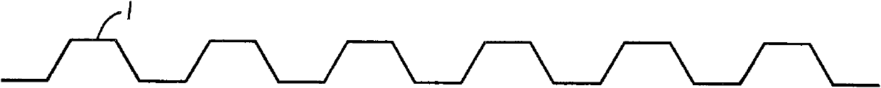
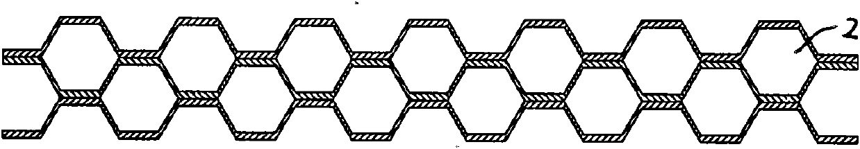
[0034] Embodiment 1: see figure 1 , 2 , 3, 4, forming a stainless steel trapezoidal corrugated plate 1 with short planes on both sides and a thickness of 0.31mm, combining adjacent ones, and fixing and superimposing them by welding to form a stainless steel honeycomb inclined tube 2 . The length of the inclined tube is 1000mm, the width is 940mm, the stack height is 250 to 1000mm, and the diameter of the honeycomb hole is 35mm.
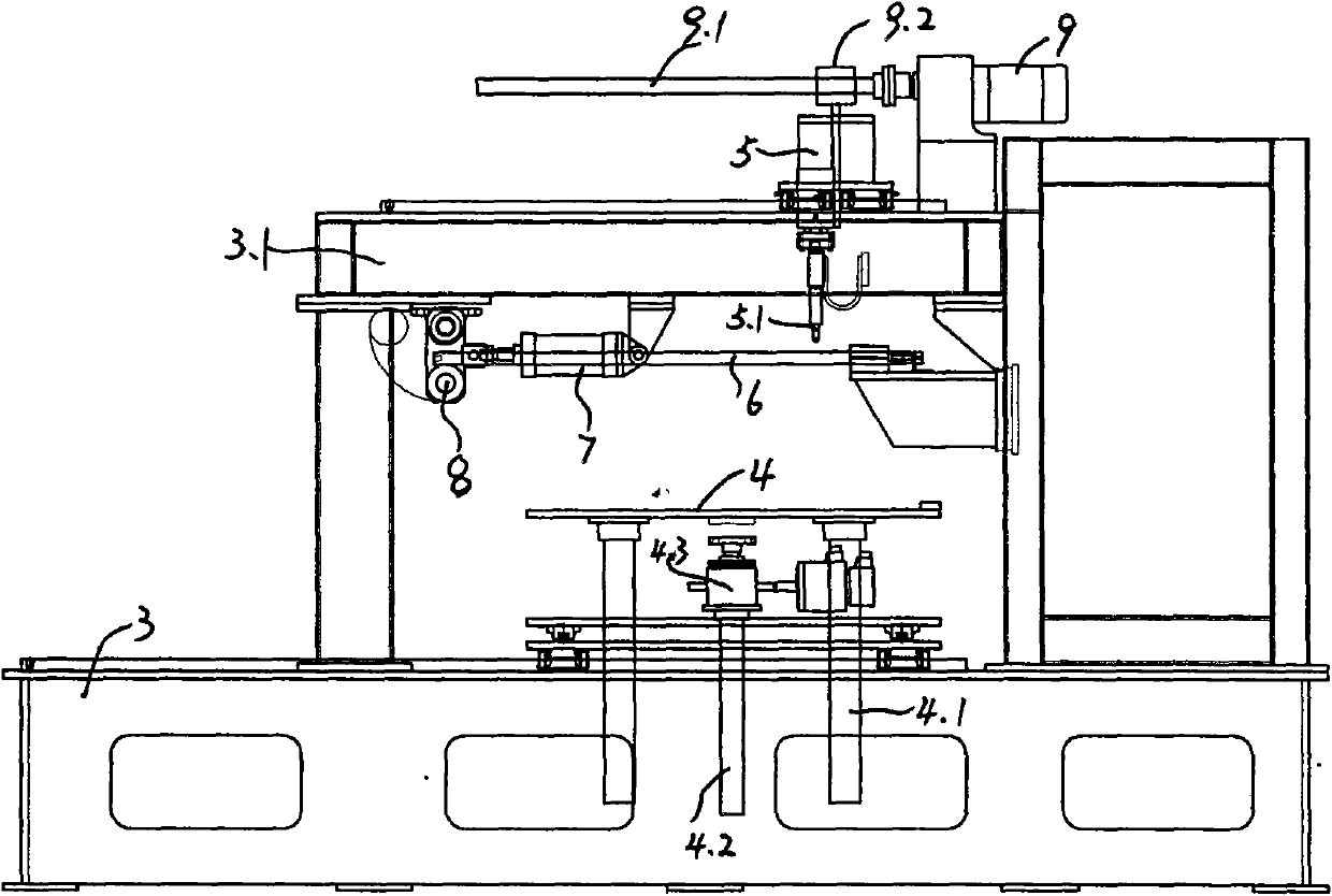
[0035] The above-mentioned honeycomb inclined tube connection welding device includes a vertical frame 3, and its upper beam 3.1 has a spot welding car 5 that moves forward and backward, and the spot welding car 5 is driven by the motor 9 above. The Sim 9.2 that cooperates and is connected with the spot welding vehicle moves back and forth, thereby driving the spot welding vehicle to move forward and backward. A plurality of spot welding heads 5.1 with the same number as the welding sides are arranged on the spot welding car, and each spot welding h...
Embodiment 2
[0037] Example 2: see Figure 5-7 , composed of honeycomb inclined tubes superimposed adjacent corrugated plates are fixed by tongue insertion, three or more elongated holes 1.11 are punched in the valley of one corrugated plate 1.1, and protruding bends are punched in the corresponding area of the other corrugated plate 1.2 Tongue plate 1.21, when combined and fixed, the punching protruding bent piece 1.21 is inserted into the elongated hole 1.11 and pulled down even if the two are plugged in 10 to connect and fix. Assembled piece by piece to the desired thickness, the stainless steel honeycomb inclined tube 2 is obtained.
PUM
 Abstract
Description
Claims
Application Information