Brazing process of ceramic vacuum pipe with diameter greater than 300mm and device

A brazing process and vacuum tube technology, applied in the direction of manufacturing tools, tubular objects, welding equipment, etc., can solve the problems of large activation effect, neutron pollution, etc., and achieve the effect of reducing stress distribution

Active Publication Date: 2010-07-07
上海克林技术开发有限公司
View PDF0 Cites 10 Cited by
  • Summary
  • Abstract
  • Description
  • Claims
  • Application Information

AI Technical Summary

Problems solved by technology

However, the activation effect of stainless steel and aluminum alloy in the state of proton radiation is very large, causing extremely serious neutron pollution to the surrounding environment.
The ceramic vacuum tube will not have an activation effect, but there is no mature process and device for brazing ceramic vacuum tubes

Method used


Image

  • Brazing process of ceramic vacuum pipe with diameter greater than 300mm and device
  • Brazing process of ceramic vacuum pipe with diameter greater than 300mm and device
  • Brazing process of ceramic vacuum pipe with diameter greater than 300mm and device

Examples


Embodiment 1

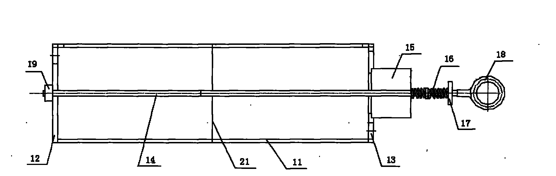
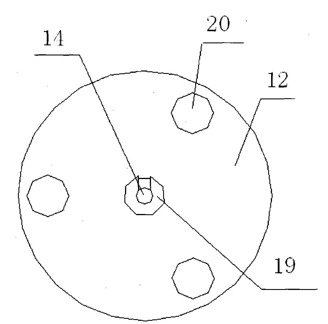
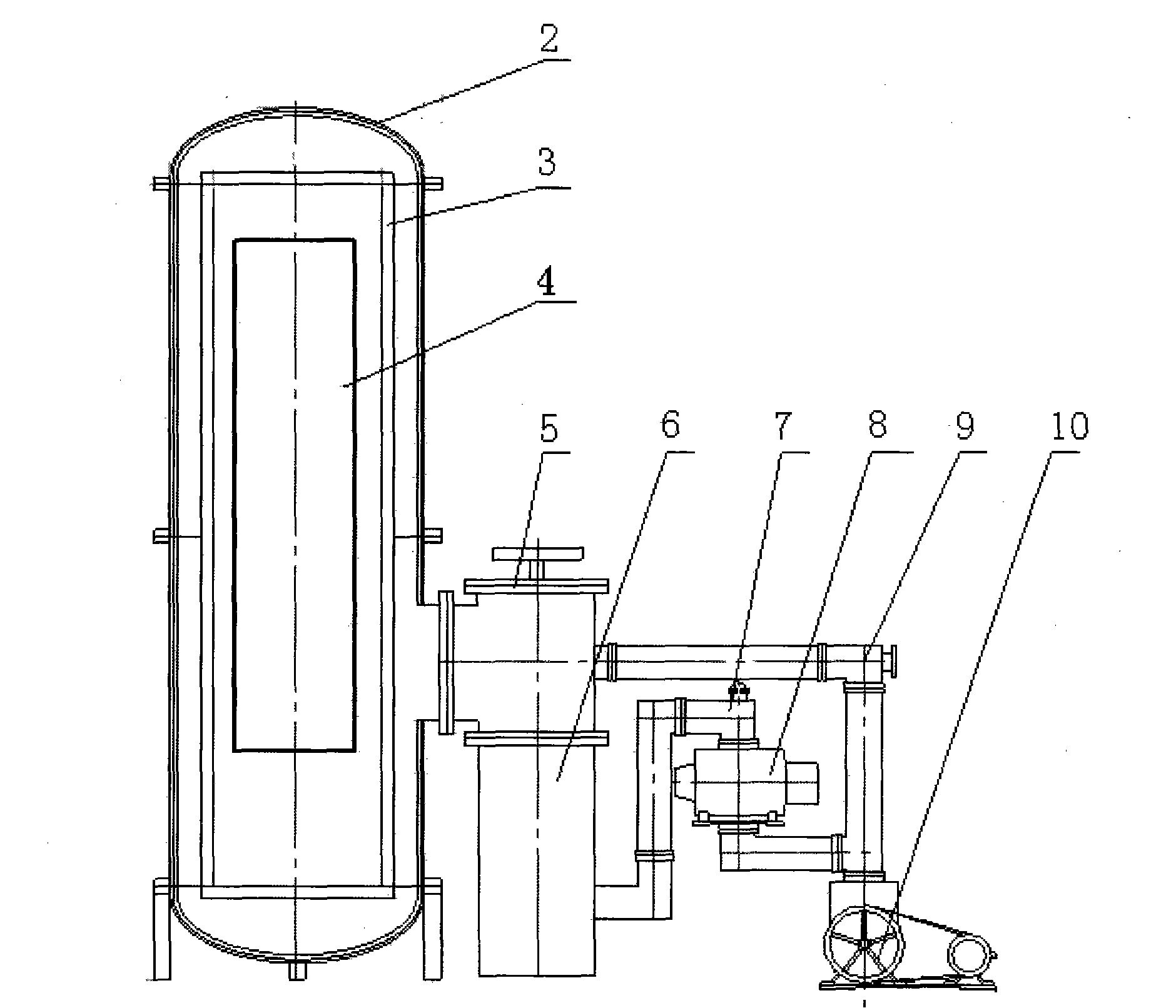
[0018] Such as figure 2 and image 3 As shown, a device for brazing ceramic vacuum tubes with a diameter greater than 300 mm provided by the present invention includes a vertical vacuum furnace body 2, a workpiece 4 is placed in the vacuum furnace body 2, and a heating system 3 is provided in the vacuum furnace body 2 , the heating system 3 is distributed around the workpiece 4, the heating system 3 is respectively connected to the controller and the power supply of the furnace body, the first valve 5 is connected to the vacuum furnace body 2, one end of the first valve 5 is connected to the diffusion pump 6, and the first valve 5 The other end of the pipe is connected to the third valve 9, the third valve 9 is connected to the mechanical pump 10, one end of the Roots pump 8 is connected to the diffusion pump 6 through the second valve 7, and the other end of the Roots pump 8 is connected to the third valve 9 Pipeline between mechanical pump 10. The heating system 3 is an e...

Embodiment 2

[0026] The device of this embodiment is the same as that of Example 1, and the difference in the steps is that the drying temperature in step 1 is 100°C and the time is 10 minutes; the drying temperature in step 2 is 100°C and the time is 10 minutes; step 4, for Vacuum the furnace until vacuum 10 -5 Start heating after Pa, raise the temperature to 510°C at 50°C / hour, keep it warm for 25 minutes, then raise the temperature to 852°C at a rate of 150°C / hour, confirm that the solder is melted, keep it warm for 25 minutes, then cool naturally to 160°C, and flush with argon Gas, out of the oven.

[0027] After testing, the vacuum leak rate at the weld of the ceramic pipe is less than 5*10- 12 Pa. M 3 / s, after a long time vacuum test, there is no crack at the joint of the pipe.

Embodiment 3

[0029] The device of this embodiment is the same as that of Example 1, and the difference in the steps is: the drying temperature in step 1 is 120°C, and the time is 5 minutes; the drying temperature in step 2 is 120°C, and the time is 5 minutes; step 4, for Vacuum the furnace until vacuum 10 -3 After Pa, start heating, raise the temperature to 500°C, keep it warm for 20 minutes, then raise the temperature to 850°C, confirm that the solder is melted, keep it warm for 20 minutes, then cool naturally to 150°C, flush with nitrogen, and take it out of the oven. The other steps in this example are the same as in Example 1. same. After testing, the vacuum leak rate at the weld of the ceramic pipe is less than 5*10- 12 Pa. M 3 / s, after a long time vacuum test, there is no crack at the joint of the pipe.


PUM

PropertyMeasurementUnit
diameteraaaaaaaaaa
diameteraaaaaaaaaa

Abstract

The invention provides a brazing process of a ceramic vacuum pipe with diameter greater than 300mm and a device, comprising the following steps: firstly, cleaning the ceramic pipe and a titanium ring, then putting them into a vacuum furnace, conducting temperature-rising weld under vacuum condition, providing shielding gas after welding, taking the ceramic pipe out from the furnace, and completing the butt-weld of two ceramic vacuum pipes. The device provided by the invention comprises a first-class mechanical rotary vane pump, a second-class Roots pump, and a third-class oil diffusion pump; the pumps are arranged in serial, meanwhile, the device is provided with a pipeline for transmitting high-purity inert gas (such as nitrogen and argon) into the furnace. The advantages of the invention are as follows: the brazing process of the ceramic vacuum pipe with diameter greater than 300mm and the device is provided, the vacuum leak rate at welded joint of the welded ceramic pipes is less than 5 * 10-12Pa. M3 / s, and no crack exists on the ceramic pipe.

Description

technical field [0001] The invention relates to a ceramic vacuum tube brazing process with a diameter greater than 300mm and a device used in the method, which is used for butt welding ceramic vacuum tubes together in a vacuum state, and belongs to the technical field of ceramic vacuum tube brazing technology and devices. Background technique [0002] At present, stainless steel and aluminum alloys are mainly used for large-diameter vacuum pipes used in domestic large-scale accelerators because the activation effect of stainless steel and aluminum alloys in the state of electron radiation is relatively small. However, the activation effect of stainless steel and aluminum alloy in the state of proton radiation is very large, causing extremely serious neutron pollution to the surrounding environment. Ceramic vacuum tubes do not have an activation effect, but there is no mature process and device for brazing ceramic vacuum tubes. Contents of the invention [0003] The object...

Claims


Application Information

Patent Timeline
Patent Type & Authority Applications(China)
IPC IPC(8): B23K1/008B23K101/06
Inventor 张红辉邵任杰蒋道满
Owner 上海克林技术开发有限公司
Why Eureka
Try Eureka