S-shaped channel type anaerobic fermentation device

An anaerobic fermentation, channel-type technology, applied in biochemical instruments, waste fuels, biochemical equipment and methods, etc., can solve problems such as difficult to achieve "continuous flow" reaction, lack of fluidity, and maintenance of anaerobic bacteria , to achieve the effect of simple and easy large discharge, promotion of fluidity, and convenient maintenance and management

Inactive Publication Date: 2010-07-07
刘明江
View PDF0 Cites 12 Cited by
  • Summary
  • Abstract
  • Description
  • Claims
  • Application Information

AI Technical Summary

Problems solved by technology

[0003] In the anaerobic fermentation devices currently used in rural areas for the characteristics of straw materials, it is difficult to achieve a "continuous flow" reaction during the fermentation process due to the low density, large volume, and lack of fluidity of the straw. Anaerobic, it is necessary to solve the problem of fluidization of straw and the maintenance of a large number of anaerobic bacteria in a fluidized state

Method used


Image

  • S-shaped channel type anaerobic fermentation device
  • S-shaped channel type anaerobic fermentation device
  • S-shaped channel type anaerobic fermentation device

Examples


Embodiment Construction

[0024] In order to make the technical means, creative features, goals and effects achieved by the present invention easy to understand, the present invention will be further described below in conjunction with specific illustrations.

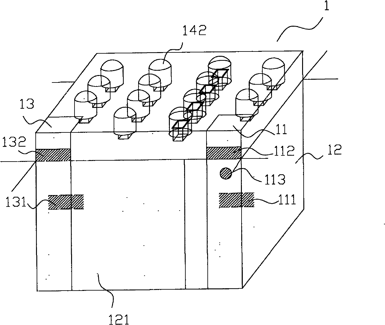
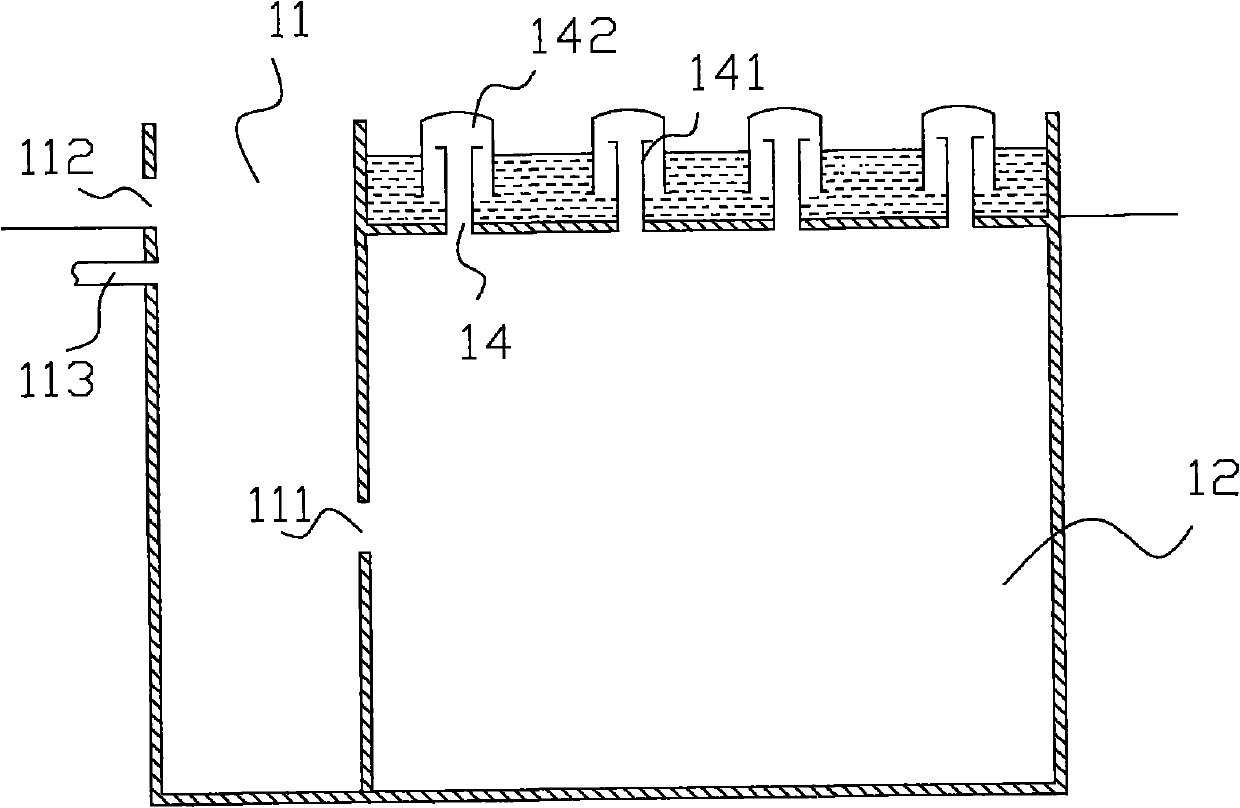
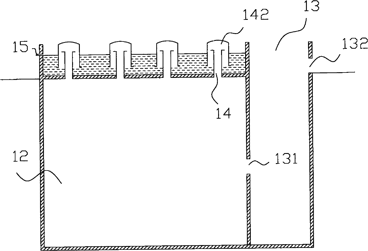
[0025] Such as figure 1 , figure 2 with image 3 Shown, a kind of S type channel type anaerobic fermentation device 1 is made of feed pool 11, anaerobic generation pool 12 and discharge pool 13, and feed pool 11, anaerobic generation pool 12 and discharge pool 13 are all made of It is made of bricks or poured with concrete, wherein the feed pool 11 and the discharge pool 13 are located on both sides of one side of the anaerobic generation pool 12, and the height of the upper end of the feed pool 11 and the discharge pool 13 is higher than that of the anaerobic generation pool. pool 12, the top of the anaerobic generation pool 12 is sealed, and three layers of partitions 121 are built in the anaerobic generation pool 12, and the three layers o...


PUM


Abstract

The invention relates to an S-shaped channel type anaerobic fermentation device relating to a fermentation device. The S-shaped channel type anaerobic fermentation device comprises a feeding pond, an anaerobic fermentation pond and a discharging pond, wherein the feeding pond and the discharging pond are positioned at one side of the anaerobic fermentation pond; the upper ends of the feeding pond and the discharging pond are higher than the anaerobic fermentation pond; the top end of the anaerobic fermentation pond is sealed; and the anaerobic fermentation pond is internally provided with a plurality of partition plates or partition walls for structuring one or more groups of S-shaped channels. Fluid substances are sufficiently subjected to anaerobic fermentation by flowing in the anaerobic fermentation pond in an ponds-shaped channel way and then discharged from an overflow opening of the discharging pond, and methane generated through the anaerobic fermentation in the anaerobic fermentation pond is discharged through a gas guide hole arranged on the top end, enters a gas storage hood and is discharged and collected along a gas guide pipeline positioned at the top end of the gas storage hood. The invention has simple structure, very convenient construction and time and material saving, can be used for large and medium methane engineering construction, lengthens the anaerobic fermentation process through S-shaped channel type arrangement and greatly promotes the flowability of the substances through a capacious S-shaped space, thereby enhancing the gas generation efficiency; and in addition, the invention has convenient later-stage maintenance and management and simple and easy normal discharging and large discharging, and is suitable for being popularized in large quantities in rural areas.

Description

technical field [0001] The invention relates to a fermentation device, in particular to an S-shaped channel type anaerobic fermentation device. Background technique [0002] At present, microbial fermentation is an effective way to obtain a large number of microbial products. Since some microorganisms are obligate or facultatively anaerobic, anaerobic fermentation devices are required. The current situation of existing anaerobic fermentation equipment is: small-scale cultivation relies on the method of anaerobic tanks or small-volume reaction bottles, and large-volume fermentation requires special fermentation equipment. In our widely used biogas fermentation collection device, it is a large-scale fermentation equipment. At the same time, in order to better obtain biogas and increase the effect of anaerobic fermentation, we need to modify the anaerobic fermentation device. [0003] In the anaerobic fermentation devices currently used in rural areas for the characteristics o...

Claims


Application Information

Patent Timeline
IPC IPC(8): C12M1/107
CPCY02E50/343C12M21/04C12M23/12Y02E50/30
Inventor 刘明江陆永成张喜民张先文秦成好
Owner 刘明江
Why Eureka
Try Eureka