Deep-well oil-extraction external flow-channel direct and reverse circulation freely-throwing jet injector oil production method and device

A technology of reverse circulation and external flow channel, applied in the directions of jet pump, production fluid, non-displacement pump, etc., can solve the problems of easy-buried packer, oil well accident, inapplicable oil well, etc., to improve theoretical production and flow channel area. increased effect

Active Publication Date: 2010-07-07
韩克楚
View PDF0 Cites 10 Cited by
  • Summary
  • Abstract
  • Description
  • Claims
  • Application Information

AI Technical Summary

Problems solved by technology

Rod pumps are not applicable to the oil wells mentioned above
Electric submersible pumps and hydraulic piston pumps in rodless pump oil production have very strict requirements on the properties and impurity content of oil well produced fluids, and are not suitable for sand, wax, and thick oil reservoirs, while hydraulic jet pumps are suitable for sand, wax, and thick oil reservoirs. However, the current hydraulic jet pumps used in oil production have the following problems: (1) the packer is easy to fail; (2) the sand producing oil well is easy to bury the packer and cause the oil well accident; (3) the free throw jet pump Difficult to achieve large displacement production; (4) Various pipe strings can only be produced in one-way positive circulation

Method used


Image

  • Deep-well oil-extraction external flow-channel direct and reverse circulation freely-throwing jet injector oil production method and device
  • Deep-well oil-extraction external flow-channel direct and reverse circulation freely-throwing jet injector oil production method and device
  • Deep-well oil-extraction external flow-channel direct and reverse circulation freely-throwing jet injector oil production method and device

Examples


Embodiment 1

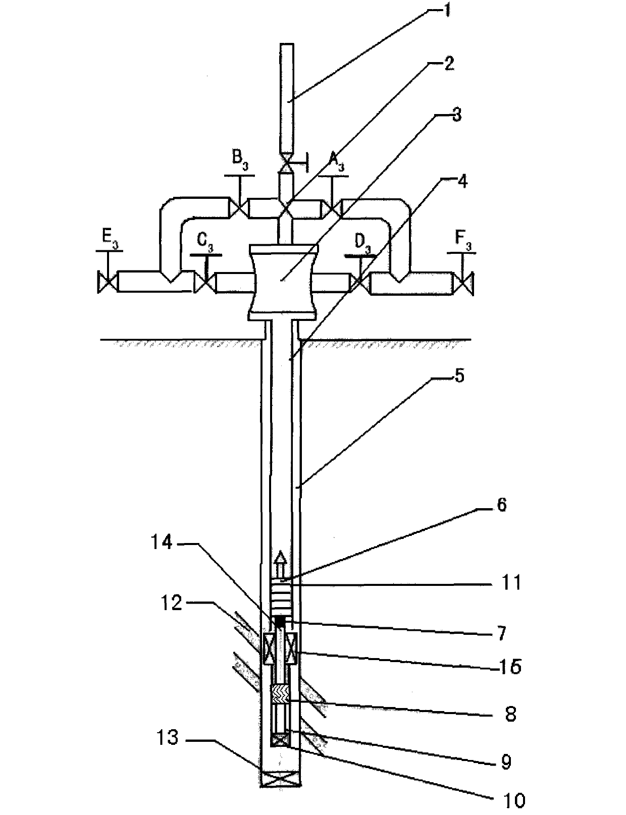
[0031] Embodiment 1: (with reference to attached image 3 ), by connecting a single oil pipe at the lower part of the wellhead device, the lower end of the oil pipe is connected with a pump barrel with an external flow channel, and a pump core (divided into positive and negative circulation pump cores) is installed in the pump barrel with an external flow channel. Install fixed reel. The combined packer and double tailpipe are connected under the pump barrel with external flow channel. The inner tailpipe is a small-diameter pipe to increase the liquid flow rate.

[0032] When positive circulation is required for oil well production, the power fluid flow channel and the pump core string are the same oil pipe. The power fluid is transferred from the downhole tubing to the positive circulation pump core in the pump barrel with an external flow channel to make the pump core work, and the pump core sucks the formation fluid into the pump core through the external flow channel of t...

Embodiment 2

[0037] Embodiment 2: (referring to attached Figure 4 ): By connecting the parallel double oil pipes at the lower part of the wellhead device, the lower end of the parallel double oil pipes; the pump barrel with external flow channels, and the pump core installed in the pump barrel with external flow channels (divided into positive and negative circulation pump cores) . Install and fix valve under the pump core. The tubing anchor and double tail pipes are connected under the pump barrel with external flow channels, and the inner tail pipes are small-diameter pipes to increase the liquid flow rate. The middle of the outer tailpipe is connected to the sand leakage pipe, and the bottom end is the tail plug.

[0038] When positive circulation is required for oil well production, the power fluid channel is put into the pump core tubing. Put the power fluid from the pump pipe to the positive circulation pump core in the pump barrel with an external flow channel to make the pump c...

Embodiment 3

[0044] Embodiment 3: with reference to attached Figure 5 , by connecting concentric double oil pipes at the lower part of the wellhead device, the lower end of the inner oil pipes of the concentric double oil pipes is connected with a pump barrel with an external flow channel, and a jet pump is installed in the pump barrel with an external flow channel (divided into positive and negative pump cores) , Install and fix the valve under the pump core. An inner sealer and a double tailpipe are installed between the bottom of the pump barrel with an external flow channel and the outer oil pipe. The inner tailpipe is a small diameter tube that increases the liquid flow rate. The middle of the outer tailpipe is connected to the sand leakage pipe, and the bottom end is the tail plug.

[0045] When positive circulation is required for oil well production, the power fluid channel is the pump core tubing-inner tubing. Put the power fluid from the inner oil pipe to the positive circula...


PUM


Abstract

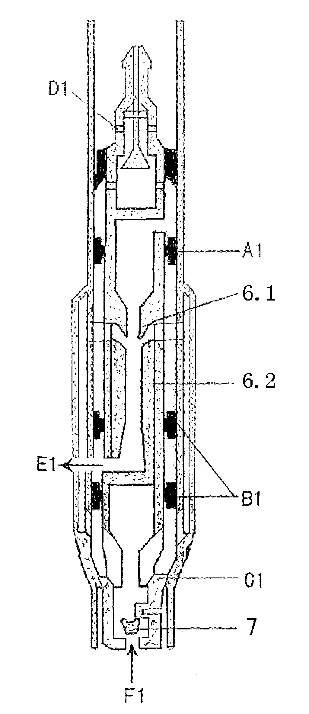
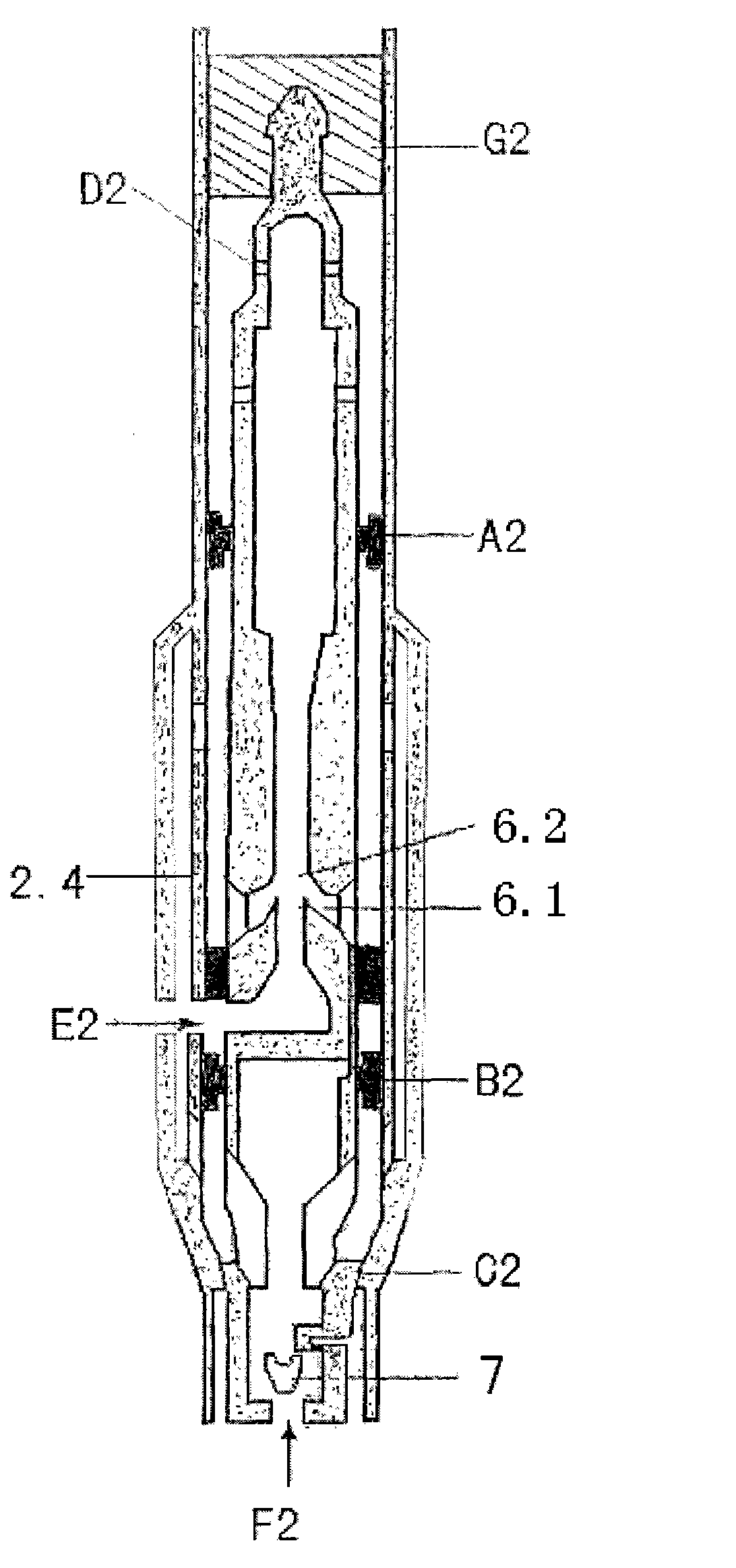
The invention relates to a deep-well oil-extraction external flow-channel direct and reverse circulation freely-throwing jet injector oil production method and a device. The oil production method comprises the following steps of: installing a pump cylinder with an external flow-channel under a well; and installing a direct circulation pump core during the direct circulation and installing a reverse circulation pump core during the reverse circulation, wherein no internal flow channel is formed in the direct circulation pump core and the reverse circulation pump core; during the direct circulation, power liquid absorbs formation liquid into the pump core through the external flow channel on the pump cylinder by a nozzle from the mouth of the well to the direct circulation pump core and after the power liquid is mixed with the formation liquid, the mixed liquid reaches the ground; and during the reverse circulation, the power liquid absorbs the formation liquid into the pump core through the external flow channel on the pump cylinder by the nozzle from the mouth of the well to the reverse circulation pump core and after the power liquid is mixed with the formation liquid, the mixed liquid reaches the ground. The method and the device have the advantages of realizing that the direct and reverse circulation production and liquid power freely throw the pump core, increasing the area of the flow channel because the formation liquid flows to the pump core from the external flow channel of the pump cylinder and increasing the theoretical yield of an oil well.

Description

1. Technical field: [0001] The present invention relates to a method and device for oil production in the petroleum industry, in particular to a deep well oil production external flow channel positive and negative circulation free start-up type suitable for sand production, waxy and heavy oil reservoirs, directional inclined wells, inclined vertical wells, and horizontal wells Jet pump oil recovery method and device. 2. Background technology: [0002] In the process of crude oil extraction, due to the influence of factors such as oil reservoir structure, crude oil physical properties, and formation water properties. New requirements are put forward for oil recovery technology. On the other hand, with the advancement of drilling technology, a large number of directional inclined wells, inclined vertical wells, and horizontal wells have been developed in land and offshore oil fields. In addition, there are a large number of eccentric wear wells in old oilfields. Rod pump oi...

Claims


Application Information

Patent Timeline
IPC IPC(8): F04F5/10F04F5/44F04F5/46E21B43/00
Inventor 韩克楚
Owner 韩克楚
Why Eureka
Try Eureka