Method for monitoring misalignment of physically cross-coupling feeding machine shafts

An orthogonal coupling and feeding technology, applied in the field of numerical control, can solve the problems of high cost, increased cost, and inability to use infrared sensors, etc., and achieve the effect of low cost and high benefit

Inactive Publication Date: 2010-07-07
SIEMENS AG
View PDF2 Cites 11 Cited by
  • Summary
  • Abstract
  • Description
  • Claims
  • Application Information

AI Technical Summary

Problems solved by technology

However, the use of vibration sensors not only increases the cost, but its installation may damage the mechanical structure
The biggest problem with using infrared sensor technology is that, for safety reasons, the mechanical transmission of most machine tools is covered by a cover and cannot use infrared sensors
However, these methods all require a large cost and require additional space to install these instruments, and the installation of these instruments may damage the structure of the machine tool itself
Also, it is more difficult to monitor the misalignment of a physically orthogonally coupled supply mechanical shaft where the entire mechanical drive train is shielded by a shield and integrated with the table
In addition, these external monitoring systems usually require technical experts and dedicated signal processing methods to complete the monitoring of system misalignment

Method used


Image

  • Method for monitoring misalignment of physically cross-coupling feeding machine shafts
  • Method for monitoring misalignment of physically cross-coupling feeding machine shafts
  • Method for monitoring misalignment of physically cross-coupling feeding machine shafts

Examples


Embodiment Construction

[0041] In order to make the object, technical solution and advantages of the present invention clearer, the present invention will be further described in detail below with reference to the accompanying drawings and examples.
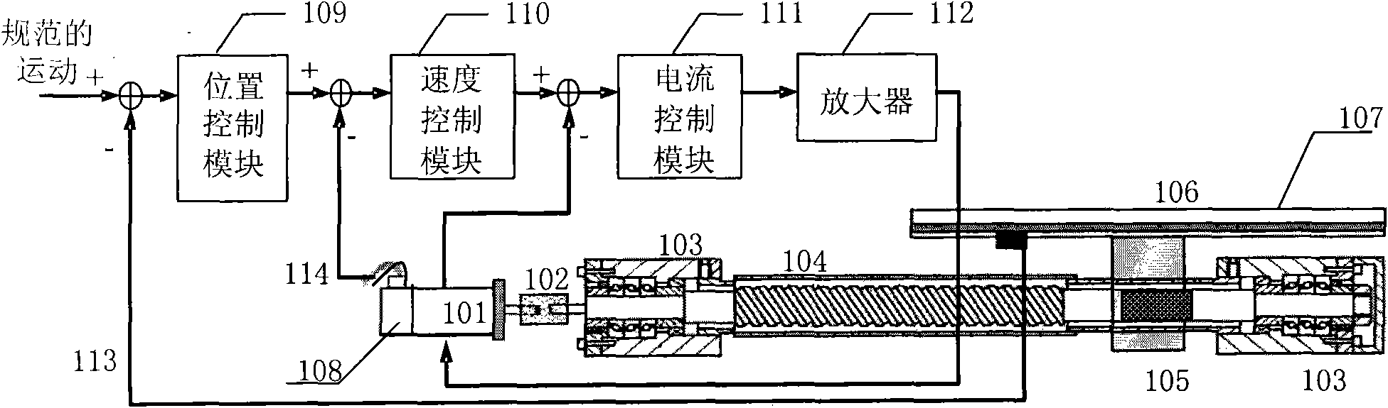
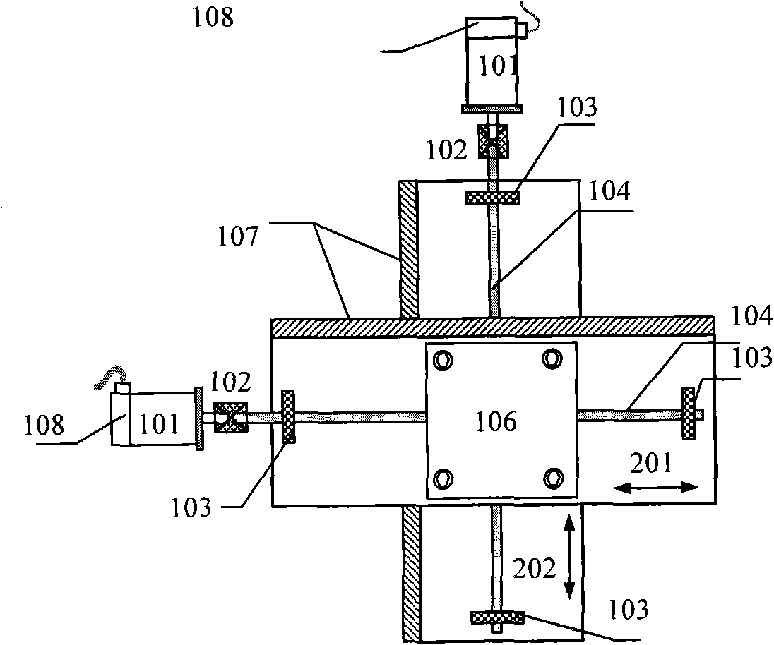
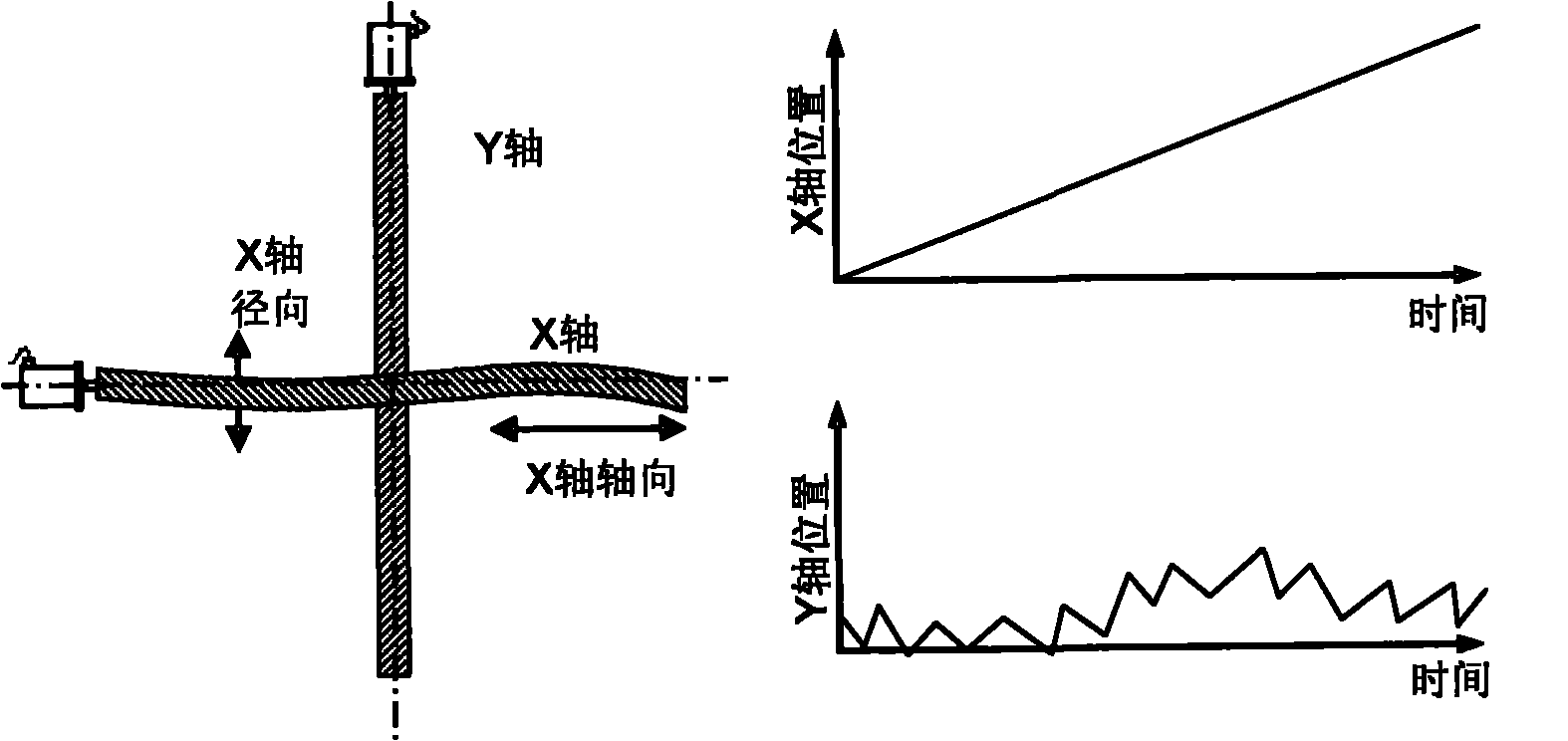
[0042] The main idea of ​​the present invention is: utilizing the characteristic that the axes of the feed machine of orthogonal coupling are perpendicular to each other in physics, when one of the axes moves, if the axis is misaligned, there will also be movement in the radial direction of the axis, so that the other The shaft will also move accordingly. Therefore, by analyzing the DMS position signal of the physically orthogonally coupled feed mechanical shaft, the vibration and displacement in the radial direction of the feed mechanical shaft can be sensed, thereby realizing the misalignment of the feed mechanical shaft. monitor. image 3 It is a schematic diagram of the principle of the method for monitoring the misalignment of physically orthogonal...


PUM


Abstract

The invention discloses a method for monitoring the misalignment of physically cross-coupling feeding machine shafts. The method comprises the following steps of: A. enabling one of the physically cross-coupling feeding machine shafts to remain stationary, enabling the other shaft to move from one end of the shaft to the other end at constant speed and recording DMS (direct position Measurement System) position signals of the two shafts; B. determining a vibration frequency characteristic value of the stationary shaft according to the DMS position signal of the stationary shaft; C. rebuilding a misaligned curve of the shaft at constant speed according to the vibration frequency characteristic value of the stationary shaft and the DMS position signals of the two shafts; and D. determining the misaligned circumstance of the shaft at constant speed according to the rebuilt misaligned curve. By adopting the invention, the misalignment-monitoring method with low cost, high benefit, intuition and simple and convenient use can be realized so as to achieve the purpose of monitoring the misalignment of the physically cross-coupling feeding machine shafts.

Description

technical field [0001] The invention relates to the technical field of CNC (Computer Numerical Control), in particular to a method for monitoring misalignment of physically orthogonally coupled feed machine axes. Background technique [0002] The feed system is one of the most important parts of a CNC machine tool. figure 1 A schematic diagram of the composition and structure of a typical feed system in a CNC machine tool is shown. see figure 1 , The feed system generally includes: a motor 101, a coupling 102, a bearing 103, a ball screw 104, a ball screw nut 105 and a table 106, etc. figure 1 It also shows the main functional modules of the machine tool control system used to control the motion of the feed system, including: the grating scale 107 in the direct position measurement system (DMS), the indirect position measurement system [0003] (IMS) motor encoder 108, position control module 109, speed control module 110, current control module 111 and amplifier 112, etc...

Claims


Application Information

Patent Timeline
Patent Type & Authority Applications(China)
IPC IPC(8): G01B21/24
Inventor 邵晓寅王青岗时文刚马维民邢建辉胡喜
Owner SIEMENS AG
Why Eureka
Try Eureka