
Intermittent power supply micropower standby control circuit

A control circuit and intermittent technology, which is applied in the direction of control/regulation system, high-efficiency power electronic conversion, and conversion equipment that can be converted to DC without intermediate conversion. , Maintain short standby time and other issues, to achieve the effect of reducing standby energy consumption, easy implementation, and low cost

Active Publication Date: 2010-07-07
SHANGHAI MUNICIPAL ELECTRIC POWER CO +1
View PDF0 Cites 23 Cited by
  • Summary
  • Abstract
  • Description
  • Claims
  • Application Information

AI Technical Summary

Problems solved by technology

[0003] In order to reduce standby power consumption, many people have proposed various solutions, which are mainly divided into three categories: 1. Use an independent power supply to maintain standby power consumption. The disadvantage is that the independent power supply itself has power consumption; 2. Use batteries to maintain standby power consumption , and provide start-up energy for booting. The disadvantage is that the life of the battery is generally not as good as that of home appliances. The rechargeable battery only has a life of about 500 times of repeated charging; 3. Use capacitors as the power supply to maintain standby power consumption and provide start-up energy for the start-up. Disadvantages The standby time is relatively short. During standby, the power stored in the capacitor is gradually consumed, and the voltage is continuously reduced. After a period of time, the remote control, mouse, and keyboard will not be able to wake up and start the home appliance.

Method used


Image

  • Intermittent power supply micropower standby control circuit
  • Intermittent power supply micropower standby control circuit
  • Intermittent power supply micropower standby control circuit

Examples


Embodiment Construction

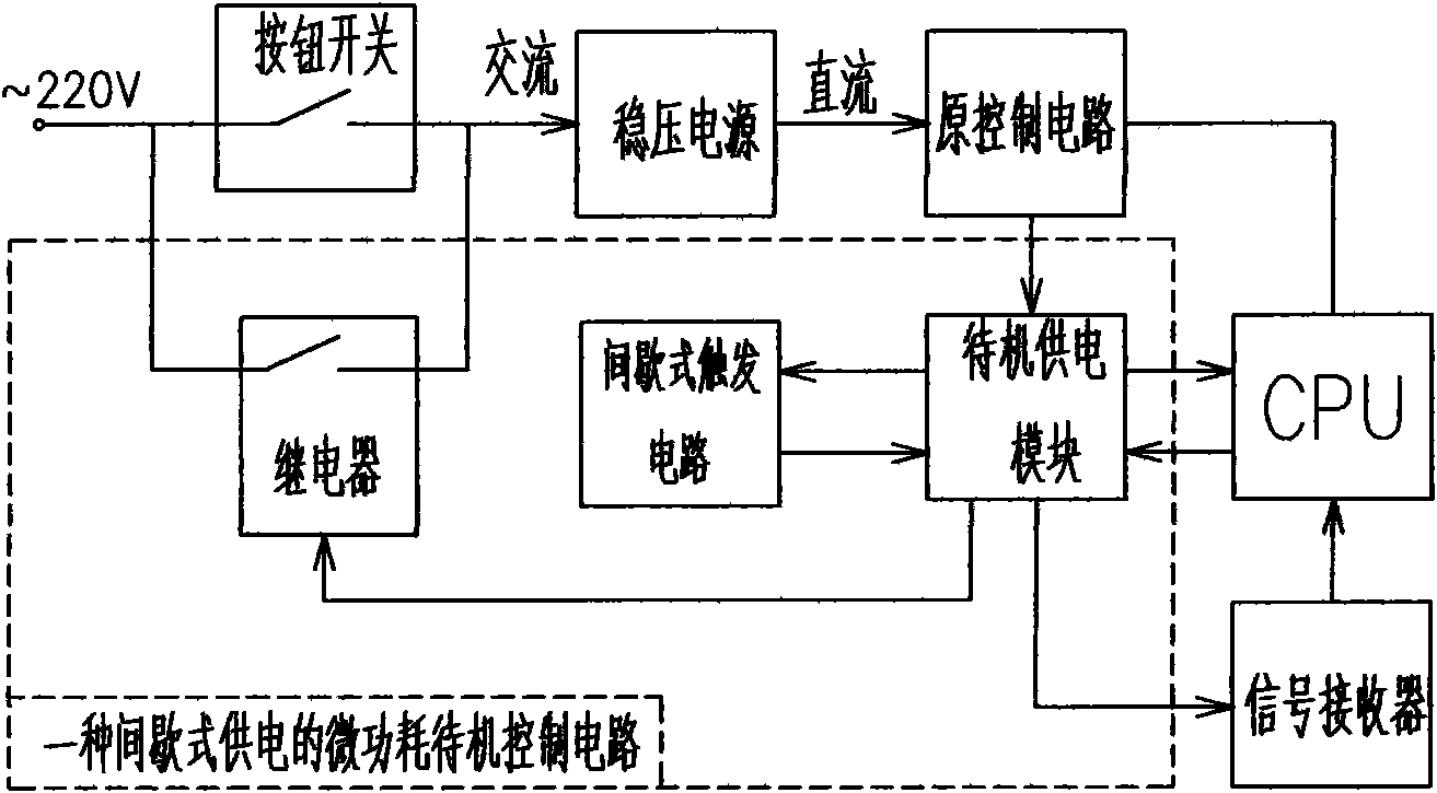
[0019] figure 1 In the dotted line square box is the circuit of the present invention, and the arrow represents the transmission direction of the electric signal, according to figure 1 It can be seen that the principle of the present invention is: when the button switch is manually pressed, the alternating current is briefly connected, the stabilized power supply works, the alternating current becomes direct current to supply power to each control circuit of the home appliance, the standby power supply module obtains electric energy, and the relay is closed when the power is turned on , turn on the mains, the home appliances work normally, the relay cuts off the AC power supply line during standby, and the power stored in the standby power supply module supplies power to the CPU and signal receiver. Whenever the power consumption reaches a certain level, the intermittent trigger circuit triggers the standby power supply module The relay control circuit in the relay is turned o...


PUM


Abstract

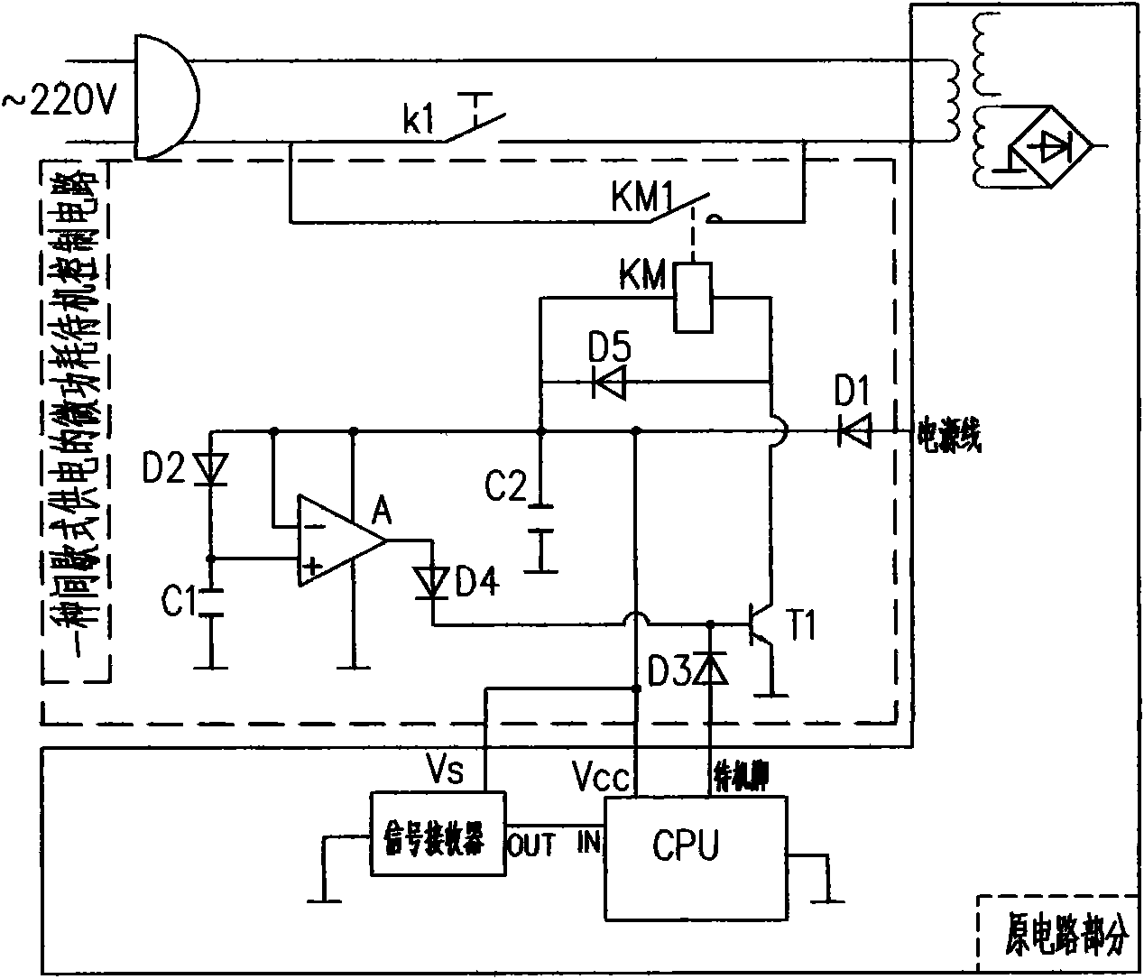
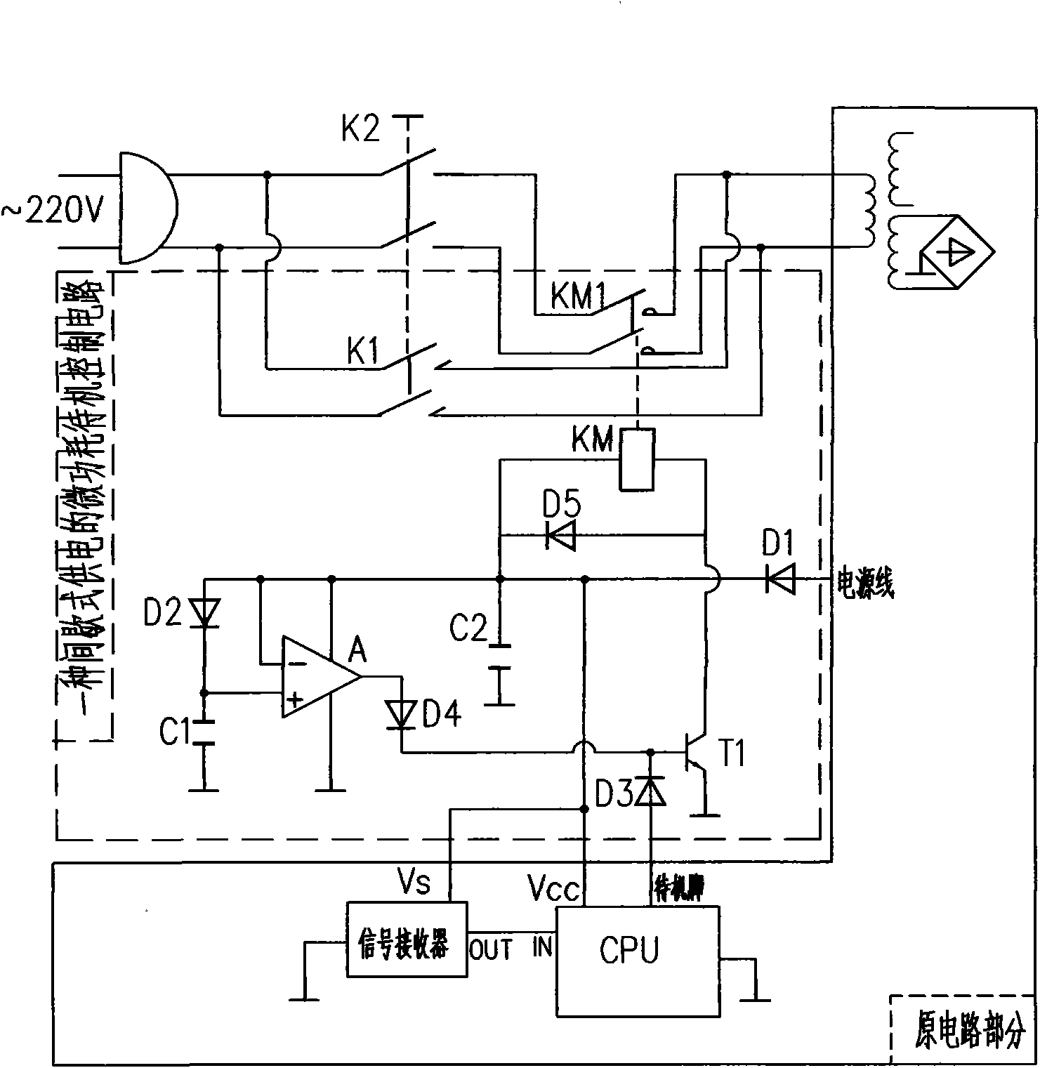
The invention discloses an intermittent power supply micropower standby control circuit comprising a stand-by power supply module, a relay and an intermittent trigger circuit, wherein the stand-by power supply module is provided with a reservoir capacitance, automatically charges when starting up and provides electric energy for a signal receiver and CPU during standby as well as provides starting electric energy for the relay; after connected in parallel, the normally open contact and the home appliance button switch are connected between mains supply and a voltage-stabilized source in series so as to cut off an alternating current power supply during standby; a voltage comparison circuit and a capacitance capable of providing reference voltage are arranged in the intermittent trigger circuit; when the voltage of the reservoir capacitance is lowered to be below the reference voltage, the trigger circuit triggers the relay to be conducted, alternating current is switched on to charge,and the relay is cut off after being charged to cut off the alternating current power supply; the step is repeated to ensure that the voltage-stabilized source can work intermittently, which has the advantages that the voltage-stabilized source works intermittently during home appliances standby so as to greatly save standby energy consumption; and the capacitance is used as a standby power supply of which the service life is longer than various batteries. The invention is suitable for electrical appliances of various standby functions.

Description

technical field [0001] The invention belongs to the field of household appliances, in particular to a micro-power consumption standby control circuit for intermittent power supply. Background technique [0002] Many household appliances, audio-visual products, computers, etc. have a standby function, and consume power when they are in standby. For example, the standby energy consumption of a computer is about 35W, and that of a color TV is about 5W. Consumption of 3% to 13% of the total. At present, the average standby energy consumption of urban households in my country has accounted for about 10% of the total energy consumption of households, which is equivalent to using a 15W-30W permanent lamp in each household. According to statistics, the annual standby energy consumption of household appliances across the country will be offset. The power generation capacity of the entire Three Gorges. Many countries have formulated corresponding policies and measures to limit and re...

Claims


Application Information

Patent Timeline
IPC IPC(8): G05F1/66H02M5/08
CPCY02B70/16Y02B70/10
Inventor 钱和革
Owner SHANGHAI MUNICIPAL ELECTRIC POWER CO
Learn More