
Heat radiating system for battery pack

A heat dissipation system and battery pack technology, applied in the direction of fuel cell heat exchange, secondary batteries, fuel cell additives, etc., can solve the problems of poor economy, high use cost, large water flow damping, etc., and achieve good heat dissipation effect and recycling Environmental protection and energy saving, solve the effect of heat dissipation and cooling

Active Publication Date: 2010-07-07
SUZHOU ANKAO ENERGY
View PDF0 Cites 9 Cited by
  • Summary
  • Abstract
  • Description
  • Claims
  • Application Information

AI Technical Summary

Problems solved by technology

The water-cooling system needs to embed water channels in each module of the power battery pack, install a set of electronically controlled water circulation pumps, and take away the heat generated by the power battery pack through the circulation of water. It is composed of several modules and most of them are stacked on top of each other. The cooling water pipe passage structure used for installation and use is complex and has many elbows, resulting in large water flow damping and slow flow in the pipe. It has high requirements on the performance of the water pump motor, and an average of 10 hours per day. For example, if a 250W DC or other water pump motor is installed on an electric vehicle, the daily power consumption required for heat dissipation is about 2.5 degrees, the cost of use is high, the economy is poor, and maintenance costs are required for long-term use. security risks

Method used


Image

  • Heat radiating system for battery pack
  • Heat radiating system for battery pack
  • Heat radiating system for battery pack

Examples


Embodiment 1

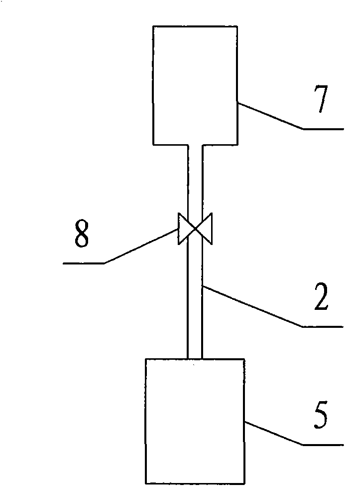
[0018] Example 1 as figure 1 As shown, the heat dissipation system of the battery pack includes a compressed gas supply source and a gas transmission pipeline, wherein the compressed gas supply source is the gas storage tank 7, the input end of the gas transmission pipeline 2 is connected to the gas storage tank, and the output end is connected to the battery box where the power battery pack is placed. 5. A one-way electric control solenoid valve 8 is installed on the gas pipeline. When working, the working compressed gas in the gas storage tank is sent to the battery box through the gas transmission pipeline to dissipate heat for the power battery pack; the pulsation control one-way electronically controlled solenoid valve can control the gas transmission state of the gas storage tank.

Embodiment 2

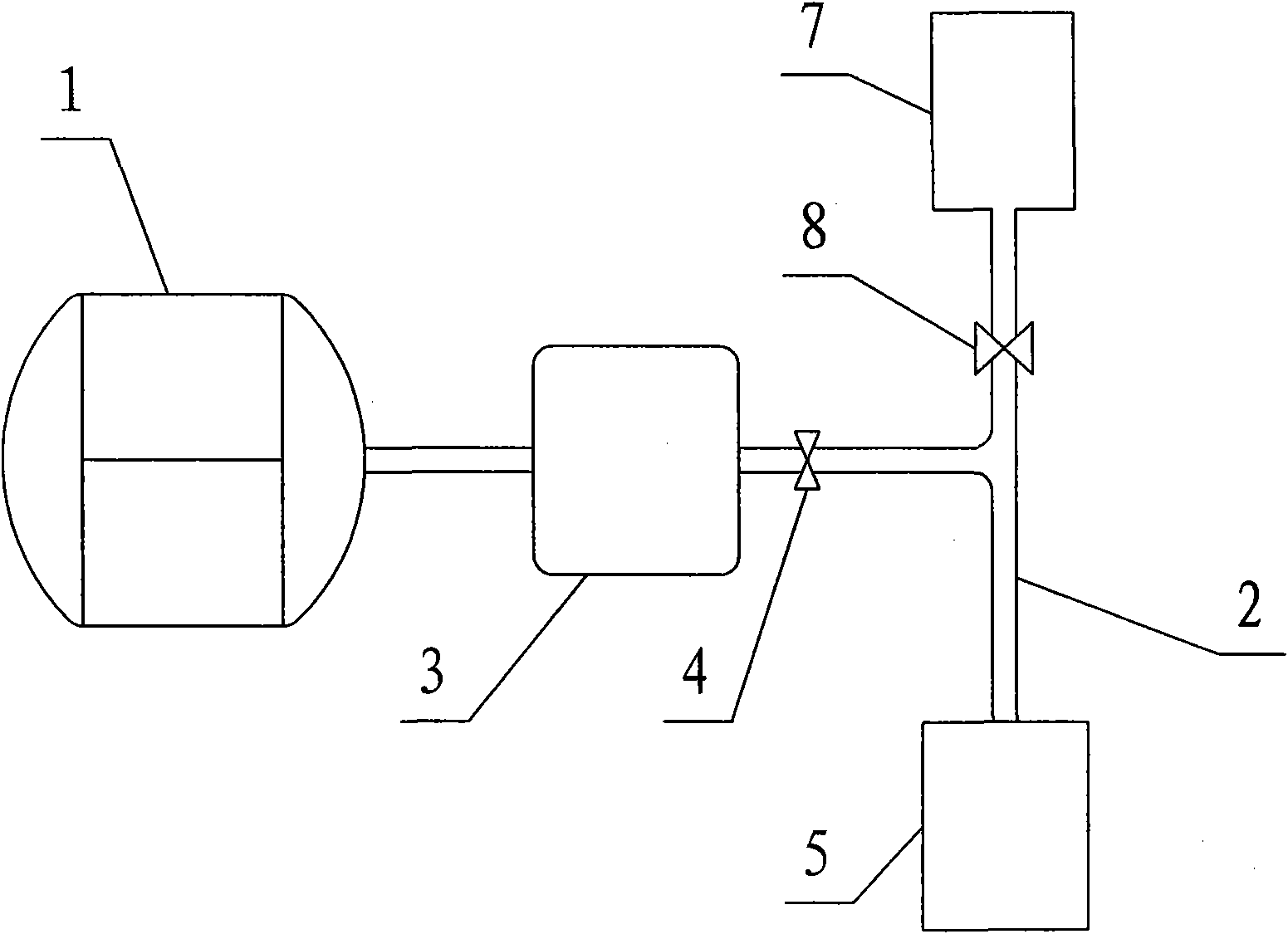
[0019] Example 2 as figure 2 As shown, the heat dissipation system of the battery pack includes a compressed gas supply source and a gas transmission pipeline 2, wherein the compressed gas supply source includes the exhaust of the brake master valve 3 and the gas supply of the air storage tank 7, and the input end of the gas transmission pipeline is divided into two branches, respectively. Connect the exhaust joint on the main brake valve 3 and the air delivery joint on the air storage tank 7, the branch air transmission pipeline connected with the air storage tank 7 is equipped with a one-way electric control solenoid valve 8, and the branch transmission line connected with the main brake valve A one-way valve 4 is installed on the gas pipeline, and the output end of the gas pipeline is connected to the battery box 5 where the power battery pack is placed. When working, the compressed gas discharged from the two gas sources is sent to the battery box through the gas pipeline...

Embodiment 3

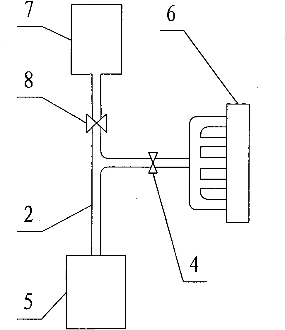
[0020] Example 3 as image 3 As shown, the heat dissipation system of the battery pack includes a compressed gas supply source and an air pipeline 2, wherein the compressed gas supply source includes an air storage tank 7 for gas supply and an electronically controlled air suspension system main valve 6 for exhaust, and the input end of the gas pipeline is branched Connect the exhaust joint on the main valve 6 of the electronically controlled air suspension system and the air delivery joint on the air storage tank 7 respectively, and the branch air delivery pipeline connected to the air storage tank 7 is equipped with a one-way electric control solenoid valve 8, which is connected with the air storage tank 7. A one-way valve 4 is installed on the branch air pipeline connected to the main valve of the electronic control air suspension system, and the output end of the air pipeline is connected to the battery box 5 where the power battery pack is placed. When working, the compre...


PUM


Abstract

The invention relates to a heat radiating apparatus of a battery, in particular to a heat radiating system for a battery pack, which is used for cooling a power battery pack on an electric motor coach. A common heat radiating system of a battery pack is strong wind cooling and water cooling: the wind cooling drives an electronic fan to blow wind or extract wind by the electricity supplied by the power battery pack, thereby increasing the working load of the battery and shortening the operation mileage of the electric motor; the water cooling is provided with a complicated cooling water pipeline and a water pump motor with high performance, so that the technical requirement is high, a hidden trouble water leakage exists, and two cooling systems cost too much for long-time use. The invention provides the heat radiating system of the battery pack with simple structure, safe use and low cost. The heat radiating system comprises a gas supplying source a gas pipeline, wherein the gas supplying source is compressed gas, the input end of the gas pipeline is connected with the supplying source of the compressed gas, and the output end is connected with a battery box for placing the battery. In the invention, the power battery pack is radiated and cooled by the compressed gas without mounting the electronic fan or being embedded with a water channel and the water pump motor.

Description

【Technical field】 [0001] The invention relates to battery cooling equipment, in particular to a battery cooling system which uses compressed gas to cool a power battery used in an electric passenger car. 【Background technique】 [0002] As a pollution-free green transportation tool, the electric bus is energy-saving and environmentally friendly, and has a very good prospect of use. Since the power battery pack on an electric bus generates heat during operation and its temperature rises rapidly, in order to make the power battery work normally, it is necessary to effectively dissipate heat and cool down the battery pack. Common cooling systems are divided into forced air cooling and water cooling. Among them, the air-cooled heat dissipation system is powered by the power battery pack, and the electronic fan is used to blow or extract air to cool the battery pack. Using an electronic fan will increase the battery workload, increase operating costs, and shorten the average daily...

Claims


Application Information

Patent Timeline
IPC IPC(8): H01M10/50H01M8/02H01M8/04014H01M10/613H01M10/6564
CPCY02E60/12Y02E60/50
Inventor 李革臣许玉林董明朱锦其
Owner SUZHOU ANKAO ENERGY
Learn More