Plasma generating device

A technology for generating device and plasma, applied in the field of ions, can solve the problems of inapplicability of material surface modification and inability to exist in a large range outside, and achieve the effect of increasing electron density and increasing the number of cations

Inactive Publication Date: 2010-07-07
NAT SPACE SCI CENT CAS
View PDF0 Cites 14 Cited by
  • Summary
  • Abstract
  • Description
  • Claims
  • Application Information

AI Technical Summary

Problems solved by technology

Therefore, most of the high-density plasma it generates is only inside the hollow cathode and cannot exist in a large area outside, which is not suitable for surface modification of materials.

Method used


Image

  • Plasma generating device
  • Plasma generating device
  • Plasma generating device

Examples


Embodiment Construction

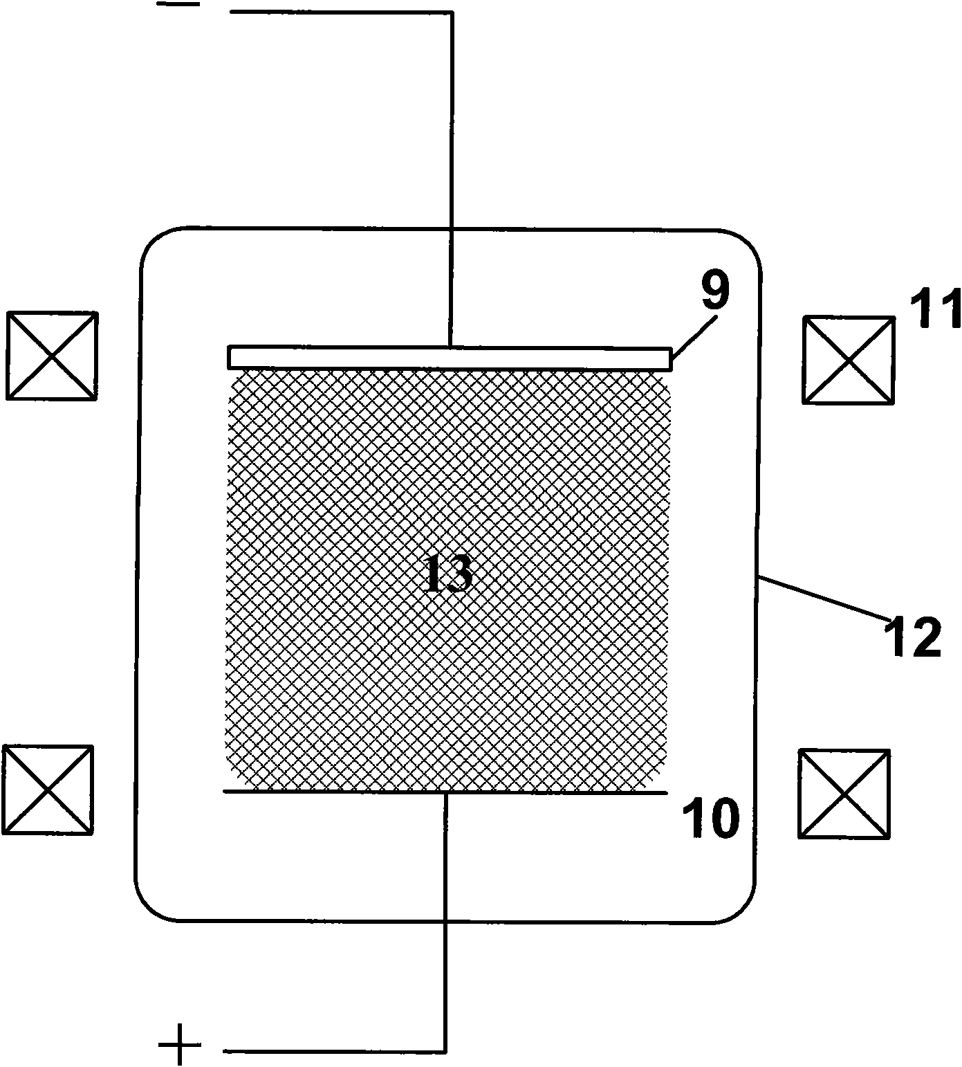
[0027] The structure of the plasma generating device in this embodiment is as follows image 3 As shown, the main part is composed of a cylindrical shell 12 , a pair of Helmholtz coils 11 , a linear hollow electrode 9 and a circular anode 10 . The Helmholtz coil 11 is placed coaxially with the casing 12, the opening of the hollow electrode 9 is opposite to the anode 10, the cathode 9 is arranged parallel to the anode 10, the center of the electrode is also at the axial center of the casing, and the inside of the casing 12 is a vacuum chamber.

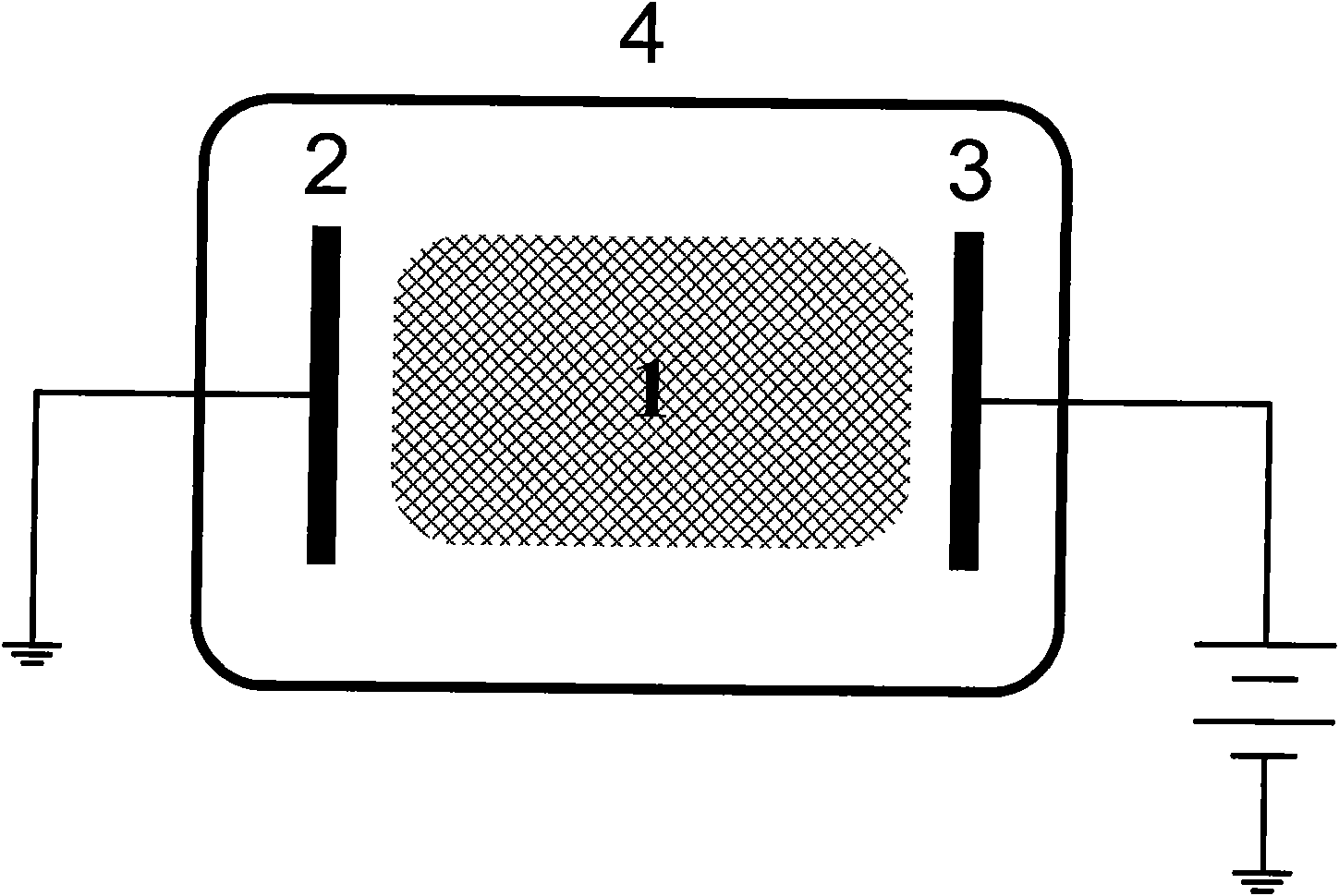
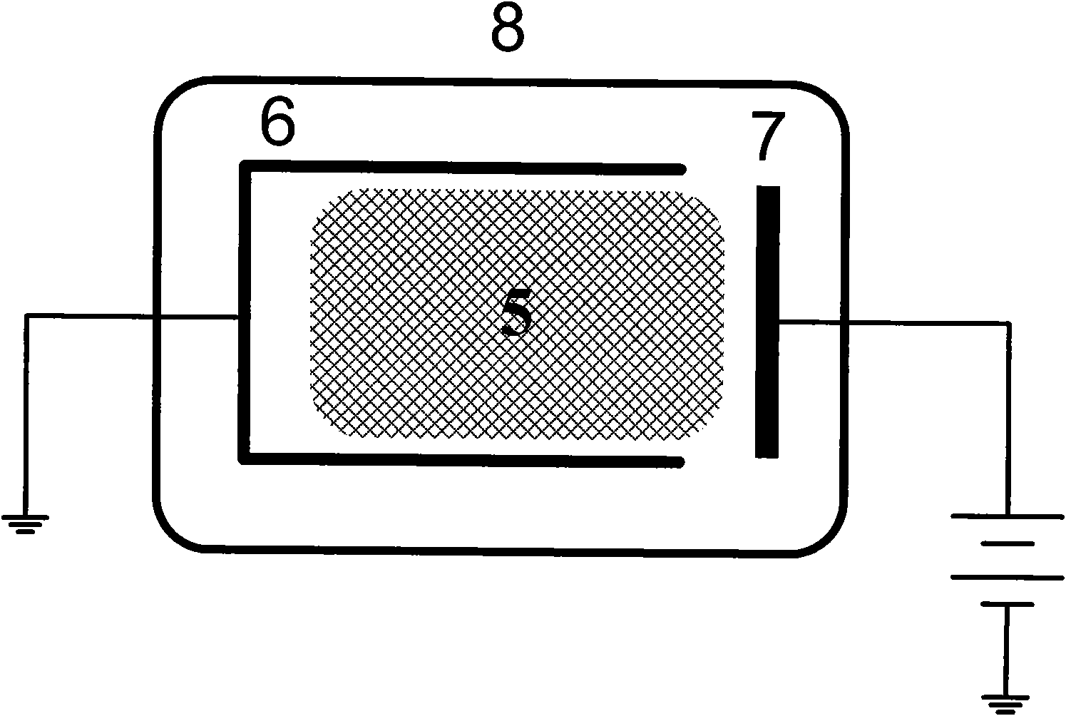
[0028] The working principle of the hollow cathode is as follows Figure 4 As shown, its structure is as Figure 5 to Figure 7 As shown, an opening slightly smaller than the diameter of the round tube is drawn on one side of the metal round tube. The width of the opening is 0.8 to 0.95 times the diameter of the inner wall of the hollow metal tube. The inner wall of the active cathode should be polished accordingly. , to avoid spark di...


PUM


Abstract

The invention discloses a plasma generating device, which comprises a shell (12), a Helmholtz coil (11), a negative pole (9), and a positive pole (10); the interior of the shell (12) is a vacuum cavity; the Helmholtz coil (11) is arranged coaxial with the shell (12); the negative pole (9) is positioned in the shell (12); the positive pole (10) is positioned in the shell (12) and opposite to the negative pole (9); the negative pole (9) is of a hollow metal tube structure with an opening along the axial direction, the opening direction is opposite to the positive pole (10), and the negative pole (9) and the positive pole (10) are arranged parallelly. In the invention, high density and large area plasma plate is generated by adopting magnetic confinement linear hollow negative pole dischargemode, thus having enhancing plasma density by hollow negative pole, and forming the uniform plasma plate (13) with density being over 10<12>cm<-3>, geometric size being over 60cm*60cm and thickness kept around 2cm. The high density and large area plasma has enormous advantage in aspects such as material surface treatment, research on interaction between plasma and electromagnetic wave, etc.

Description

technical field [0001] The invention relates to the field of plasma, in particular to a plasma generating device. Background technique [0002] Plasma technology has been applied in many fields such as materials, electronics, environmental protection, medicine, military, etc., many of which require large-scale, high-density plasma. Therefore, how to improve these parameters is the focus of research on plasma generation technology. [0003] DC discharge is the earliest and simplest way to generate plasma. Such as figure 1 , the electrode 2 is the cathode, and the electrode 3 is the anode, both of which are located in the vacuum cavity 4 . Applying a certain DC voltage under certain vacuum conditions will accelerate the charged particles randomly appearing in the gas to obtain energy. The accelerated charged particles collide with neutral gas molecules to ionize the gas molecules to generate more charged particles. The new charged particles will gain energy under the actio...

Claims


Application Information

Patent Timeline
Patent Type & Authority Applications(China)
IPC IPC(8): H05H1/50H01J37/32
Inventor 程芝峰徐跃民孙海龙吴逢时丁亮王之江孙简
Owner NAT SPACE SCI CENT CAS
Why Eureka
Try Eureka