Lightweight composite column, lightweight composite beam and load bearing lightweight composite thermal-insulation wall body

A composite wall and composite column technology, applied in the direction of heat preservation, walls, columns, etc., to achieve the effect of light weight, convenient prefabrication and installation, and good heat preservation

Inactive Publication Date: 2010-07-14
吴淑环
View PDF3 Cites 16 Cited by
  • Summary
  • Abstract
  • Description
  • Claims
  • Application Information

AI Technical Summary

Problems solved by technology

[0004] The purpose of the present invention is to provide a light composite beam, a light composite column and a load-bearing light composite thermal insulation wall to solve the technical problem that the flexible wall of the polymer thermal insulation board can also bear a large load when it is used in a small building. In the construction of new countryside, energy-saving buildings with low energy consumption can be built at low cost and clay bricks are not used.

Method used


Image

  • Lightweight composite column, lightweight composite beam and load bearing lightweight composite thermal-insulation wall body
  • Lightweight composite column, lightweight composite beam and load bearing lightweight composite thermal-insulation wall body
  • Lightweight composite column, lightweight composite beam and load bearing lightweight composite thermal-insulation wall body

Examples


specific Embodiment approach 1

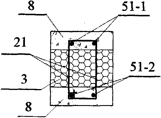
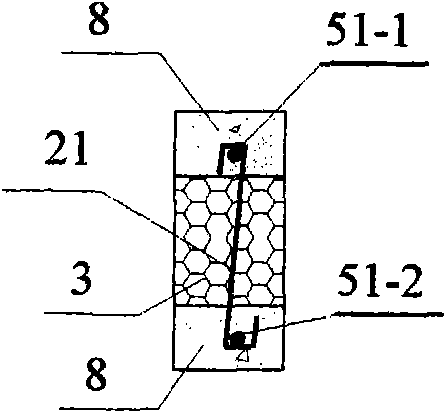
[0037] Specific implementation mode one: see figure 1 , figure 2 , a light composite column in this embodiment is composed of indoor longitudinal reinforcement 51-1, outdoor longitudinal reinforcement 51-2, steel hoop 21, core layer 3, and protective layer 8; the indoor longitudinal reinforcement 51-1, outdoor longitudinal reinforcement 51-2 are respectively located in the indoor and outdoor protective layers 8, the core layer 3 is located in the middle of the indoor and outdoor protective layers 8, the core layer 3 is bonded to the protective layers 8 on both sides; the steel hoop 21 is connected to the indoor longitudinal The steel bars 51-1 and the outdoor longitudinal steel bars 51-2 are connected and fixed to form a light-weight composite column with thermal insulation and broken bridges; the core layer 3 is a polymer insulation board, or a mineral wool board or a plant straw board or a paper honeycomb board or Perlite mortar, the protective layer 8 is cement mortar or ...

specific Embodiment approach 2

[0042] Specific implementation mode two: see Figure 5 , Figure 6 The difference between this embodiment and the first embodiment is that the protective layer 8 is located on three sides of the core layer 3 (see Figure 5 ), or the protective layer 8 is positioned around the core layer 3 and wraps the core layer 3 (see Figure 6 ), forming a light composite column with thermal bridges with protective layers on three or four sides.

[0043] If it is troublesome to prefabricate the light composite column with heat bridge, you can prefabricate the light composite column with thermal insulation bridge first, and then plaster the exposed core layer for protection after installation. Lightweight composite columns with thermal bridges can be used in non-heating areas, and can also be used for columns with low bearing capacity, such as balcony outer corner columns, decorative columns, etc.

specific Embodiment approach 3

[0044] Specific implementation mode three: see Figure 8 , the difference between this embodiment and specific embodiment 1 or 2 is that this embodiment uses alkali-resistant mesh cloth 5-1 instead of steel hoop 2; alkali-resistant mesh cloth 5-1 is pasted on the outside of protective layer 8, and the protective layer is wound and bound 8, and the core layer 3 and the indoor longitudinal reinforcement 1-1 and the outdoor longitudinal reinforcement 1-2 in the winding and bundling protective layer 8.


PUM

PropertyMeasurementUnit
heightaaaaaaaaaa
thicknessaaaaaaaaaa
widthaaaaaaaaaa

Abstract

The invention discloses a lightweight composite column, a lightweight composite beam and a lightweight composite thermal-insulation wall body. The invention relates to a composite thermal-insulation wall body for buildings. The purpose of the invention is to increase the bearing capacity of the lightweight composite thermal-insulation wall body and to cancel thermal bridges at openings. The lightweight composite column is formed by steel bars, a core layer, steel hoops and a protective layer, wherein the core layer is arranged between an internal protective layer and an external protective layer and is bonded with the internal protective layer and the external protective layer, the steel bars are arranged in the internal protective layer and the external protective layer and the steel hoops are tightly tied with the steel bars. The lightweight composite beam is formed by steel bars, a core layer, a protective layer and an alkali-resisting mesh, wherein the protective layer is arranged on the two sides and the upper part of the core layer and is bonded with the core layer; and the steel bars and the protective layer are wrapped and wound by the alkali-resisting mesh. The lightweight composite wall body is formed by beams or slabs of the main body structure of a building, lightweight composite columns, lightweight composite beams, lightweight boards and a leveling blanket, wherein the lightweight composite columns are anchored with the beams or slabs of the main body structure of the building, and the lightweight boards are arranged on the beams or slabs and are bonded with the columns; and the lightweight composite beams are arranged at openings and are connected with the lightweight composite columns. The composite wall body of the invention has the advantages that the thermal insulation performance is good, the manufacturing cost is low, the application scope is wide, the wall body reformation is promoted and the energy is saved.

Description

technical field [0001] The invention relates to a light composite column, a light composite beam in the construction field, and a load-bearing light composite thermal insulation wall composed of the light composite beam, the light composite column and a light core plastered filling wall. Background technique [0002] In the current construction of new rural areas, various new types of walls have emerged, among which there are many hidden dangers, such as thin-walled steel without hot-dip galvanizing (usually with a section of 100×100mm and a wall thickness of less than 3mm). As wall columns, with a spacing of 3-4m, install foamed benzene boards, EPS boards or straw boards between the thin-walled steel wall columns, and plaster with cement mortar on the outside of the EPS boards or straw boards. The problems are: 1. The wall columns of thin-walled steel will corrode quickly within a few years; 2. The wall body has poor rigidity and is not safe; 3. The wall body is easy to cra...

Claims


Application Information

Patent Timeline
Patent Type & Authority Applications(China)
IPC IPC(8): E04B1/80E04C3/30E04C3/29E04B2/56
Inventor 吴淑环
Owner 吴淑环
Why Eureka
Try Eureka