Composite masonry wall

A masonry wall and wall technology, applied in the structural field of building composite masonry walls, can solve the problems of poor seismic and shear resistance, inability to give full play to the compressive bearing capacity of plastered surfaces, unfavorable building earthquake resistance, etc., to achieve The effect of reducing construction cost, increasing shear resistance, and increasing indoor usable area

Inactive Publication Date: 2010-07-14
吴淑环
View PDF0 Cites 3 Cited by
  • Summary
  • Abstract
  • Description
  • Claims
  • Application Information

AI Technical Summary

Problems solved by technology

The present invention aims at the problem that the current common masonry wall has poor anti-seismic and anti-shear ability, which is unfavorab

Method used


Image

  • Composite masonry wall
  • Composite masonry wall
  • Composite masonry wall

Examples


specific Embodiment approach 1

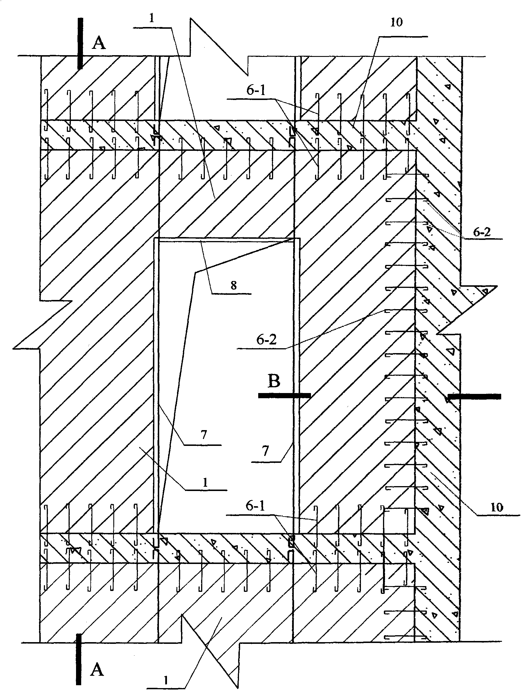
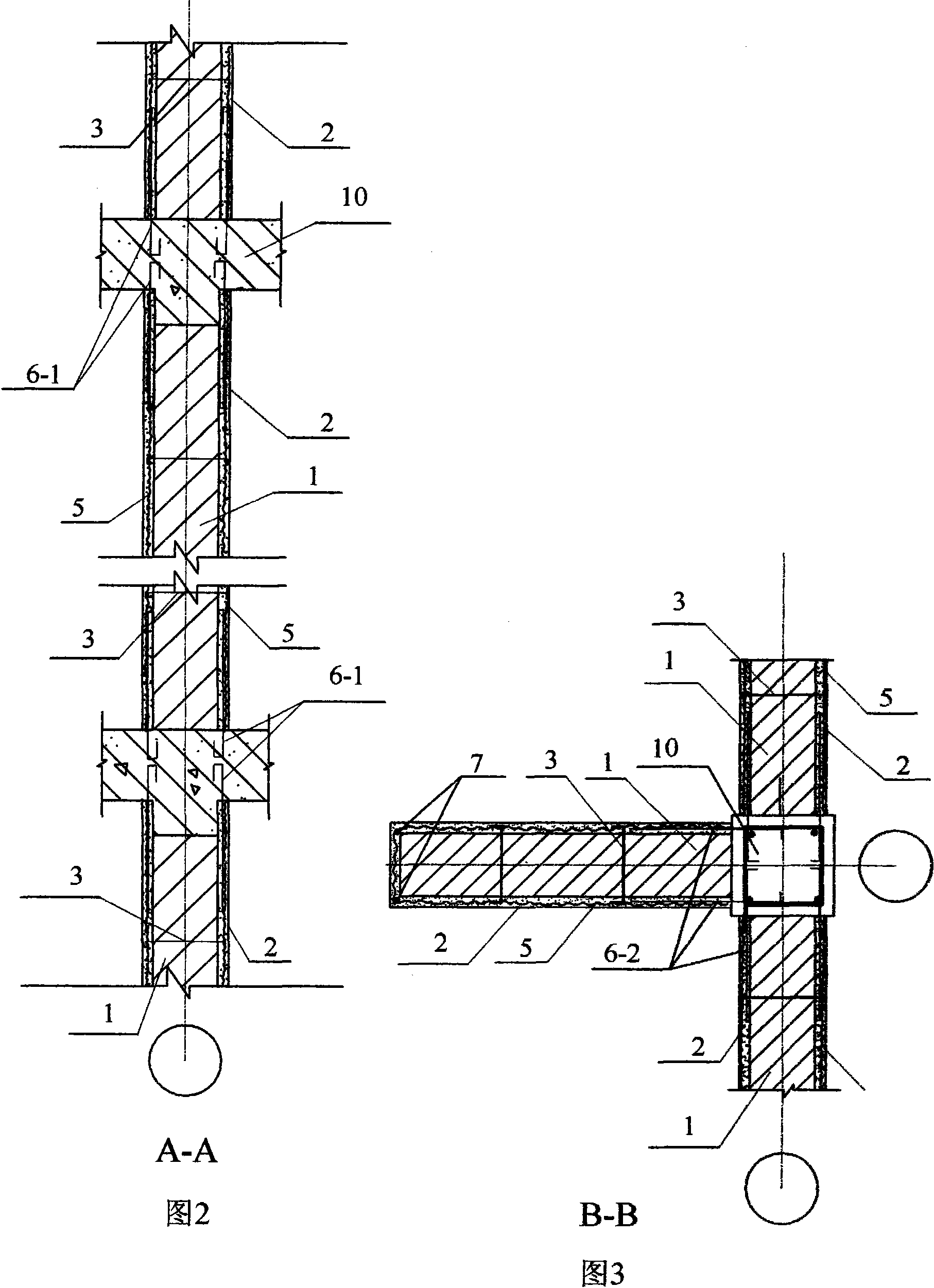
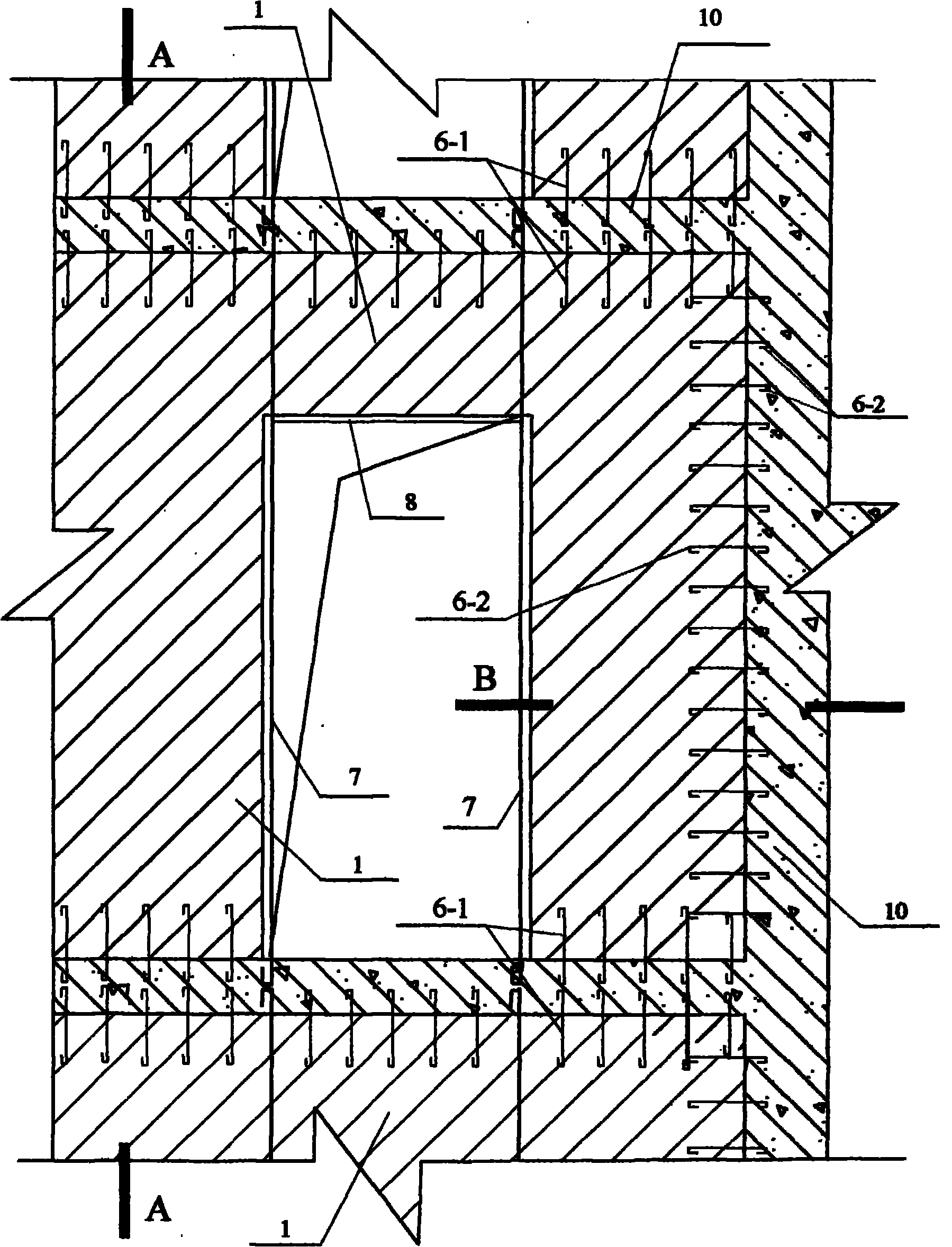
[0011] Specific implementation mode one: see Figure 1 ~ Figure 3 , a combined masonry wall of the present embodiment is composed of a masonry wall 1, an outer plastering layer 2, a tensioned steel bar 3, a mesh tensile material 5, a vertical anchoring steel bar 6-1, and a main building structure 10; The masonry wall 1 is a load-bearing masonry; the outer plastering layer 2 is a cement mortar surface layer or a fine stone concrete surface layer, or a modified cement mortar surface layer or a concrete surface layer; the mesh tensile The material 5 is an alkali-resistant mesh cloth 5-1 or a metal mesh 5-2 or a bamboo reinforcement mesh 5-3; the main building structure 10 is a beam or a plate or a column or a wall of a concrete or steel-concrete combination or a steel structure; the The tensioned steel bar 3 is located in the mortar layer of the masonry wall 1, the tensioned steel bar 3 passes through the plane of the masonry wall 1 vertically, and the tensioned steel bar 3 and t...

specific Embodiment approach 2

[0017] Specific implementation mode two: see figure 1 , image 3 The difference between this embodiment and the first embodiment is that this embodiment adds a horizontal anchoring steel bar 6-2, and the horizontal anchoring steel bar 6-2 is combined with the concrete or steel-concrete structure of the building main structure 10 or the column or steel structure The wall is anchored, and the horizontal anchoring steel bar 6-2 is overlapped with the mesh tensile material 5 .

[0018] The composite masonry wall of Embodiment 1 or 2 is a composite masonry provided with vertical and horizontal metal wires (or alkali-resistant mesh cloth or bamboo reinforcement mesh), and is connected with the main structure through anchoring steel bars. Under the action of shear force, the steel bars or metal wires (or alkali-resistant mesh or bamboo reinforcement mesh) in the wall are in tension, so the vertical and horizontal wires (or alkali-resistant mesh or bamboo reinforcement mesh) can play...

specific Embodiment approach 3

[0019] Specific implementation mode three: see Figure 1 ~ Figure 3 , the difference between this embodiment and the specific embodiment 1 or 2 is: the masonry wall 1 of a combined masonry wall in this embodiment is a light-weight filled masonry, forming a light-weight filled masonry with mesh plastering on both sides. Composite masonry walls.

[0020] This embodiment is suitable for lightweight filled walls with frame structures. The lightweight filled composite masonry walls with net plastering on both sides are shear-resistant walls with the ability to resist horizontal displacement, and their shear resistance capacity is (or alkali-resistant mesh or bamboo reinforcement mesh) the shear bearing capacity of the outer plaster layer.

[0021] The outer plastering layer on the overlapping parts of the mesh tensile material and the vertical anchoring steel bars, the outer plastering layer on the overlapping parts of the horizontal anchoring steel bars, and the outer plastering ...


PUM


Abstract

A composite masonry wall relates to a building composite wall and aims at the problem that the existing masonry has low shearing resistance bearing capacity. The building composite wall comprises a masonry wall, an external floated coat, a tie bar, alkali-resisting meshes or a metal net bamboo or a reinforcement net, a vertical anchoring steel bar and a building main body structure, wherein the masonry wall is a bearing masonry; the external floated coat is a cement mortar surface course or a fine stone concrete pavement; the building main body structure is a concrete or reinforced cement combination or a steel structural girder or plate or pillar or wall; the tie bar is arranged in the mortar layer of the masonry wall; the tie bar vertically passes through the masonry wall and is mutually pulled with alkali-resisting meshes at both sides or the metal net or the reinforcement net; the vertical anchoring steel bar is anchored with the building main body structure; and the vertical anchoring steel bar and the alkali-resisting meshes or the metal net or the reinforcement net are buried in the external floated coat, or the alkali-resisting meshes are adhered on the surface of the external floated coat, thus forming the composite bearing masonry wall with lath and plaster at both sides. The building composite wall is beneficial to the building seismic resistance, reduces the construction costs and increases the indoor usable floor area.

Description

technical field [0001] The invention relates to a structure of a building combined masonry wall. Background technique [0002] The current "Code for Design of Masonry Structures" GB50003 stipulates in the construction of composite masonry that the diameter of the vertically stressed reinforcement of composite masonry should not be less than 8mm, and the thickness of the mortar surface layer should be 30-45mm. The purpose of composite masonry is to increase the compressive bearing capacity of masonry. Due to the thicker mortar layer and more steel bars, construction is inconvenient. Composite masonry is rarely used in new construction. Composite masonry is mainly used in reinforcement projects middle. [0003] Ordinary masonry walls are brittle materials. In the seismic design of masonry, the shear strength design value of masonry is multiplied by the normal stress influence coefficient ξ N , as the design value of the seismic and shear strength of the masonry, the ξ of the...

Claims


Application Information

Patent Timeline
IPC IPC(8): E04B2/00E04B2/56E04B2/02E04C5/01
Inventor 吴淑环陆平
Owner 吴淑环
Why Eureka
Try Eureka