Deeply buried iron mineral resource underground mining and concentrating integration system

A technology of mineral resources and deep burial, applied in underground mining, underground chambers, ground mining, etc., can solve problems such as immature technical solutions and impossibility of implementation, achieve shortening of lifting and filling effects, reduce mining costs, and solve environmental pollution problems Effect

Active Publication Date: 2010-07-14
NORTHEASTERN UNIV
View PDF5 Cites 23 Cited by
  • Summary
  • Abstract
  • Description
  • Claims
  • Application Information

AI Technical Summary

Problems solved by technology

This shows that the above-mentioned disclosed technical scheme for implementing underground mining is immature and cannot be implemented

Method used


Image

  • Deeply buried iron mineral resource underground mining and concentrating integration system
  • Deeply buried iron mineral resource underground mining and concentrating integration system
  • Deeply buried iron mineral resource underground mining and concentrating integration system

Examples


example 1

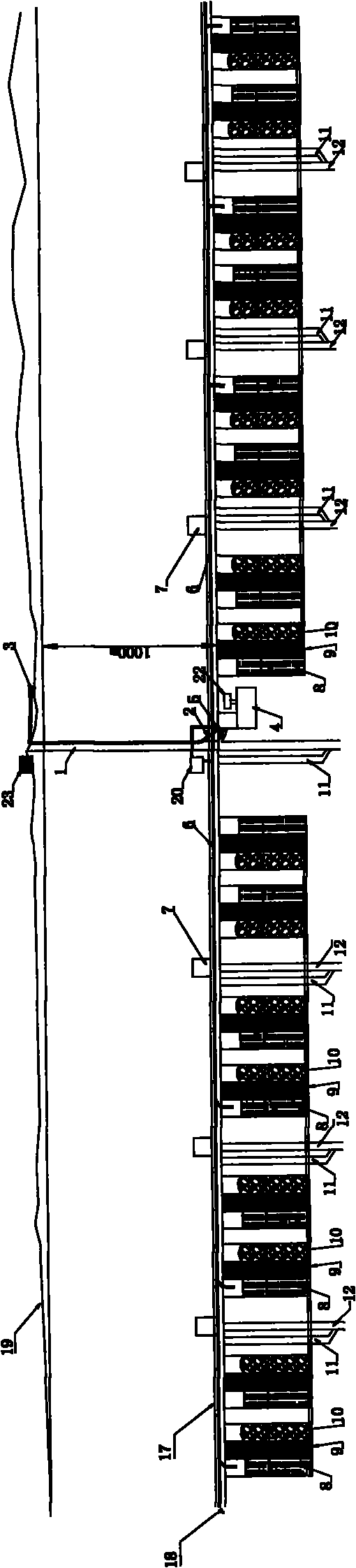
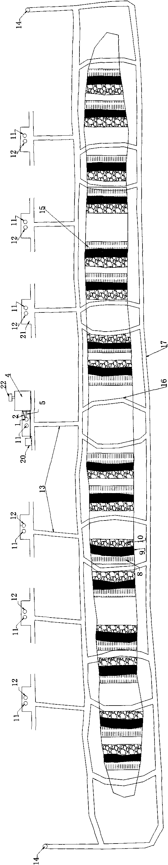
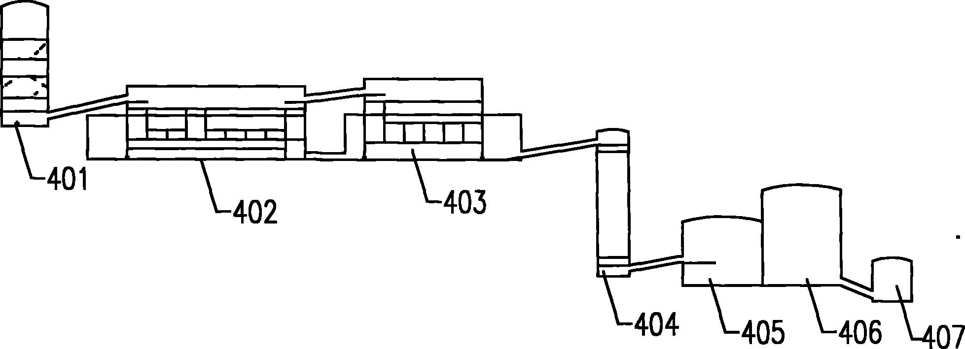
[0023] Example 1. Taking an iron mine in Benxi, my country as an example, the calculated storage capacity is 3.1 billion tons, buried 1000-1400m underground, with a total length of 2000m and a width of 1300m. Based on an annual production capacity of 25 million tons, the integrated system of underground mining and selection is formed, such as figure 1 with figure 2 As shown, in the direction of the vertical ore body, a main lift shaft 1 is set at a position 50m away from the surface movement zone, and a main lift shaft 1 is set in the area 20-300m to the left of the main lift shaft 1 and 20m below the main transportation horizontal roadway 17. Underground concentrator 4, including gyratory chamber 401, conical chamber 402, screening chamber 403, powder ore chamber 404, ball mill chamber 405, sorting chamber 406, product conveying chamber 407, each chamber adopts a plane arrangement, such as image 3 with Figure 4 shown. The design space of the gyratory chamber 401 is 18m...

example 2

[0025] Example 2: Taking the Sijialing Iron Mine in my country as an example, the mineral resource is buried below 600m underground, the ore body is 1000m long and 500m wide, and its reserves are calculated to be 1.6 billion tons. According to the annual production capacity of 10 million tons, the formation of the underground mining and selection integrated system of the present invention is the same as Example 1. The difference is that, in the direction of the vertical ore body and delineated at the position of 30m in the surface movement zone, a main hoisting shaft 1 is set up, and an underground mineral processing plant 4 is set up on the left side of the main hoisting shaft 1 and 40m below the main transportation horizontal roadway 17. The underground mineral processing The space of each chamber in Plant 4 is arranged in a trapezoidal form. Such as Figure 5 with Image 6 shown. The design space of gyratory chamber 401 is 18m×70m×40m, +30m maintenance space, the conical...


PUM


Abstract

The invention relates to a deeply buried iron mineral resource underground mining and concentrating integration system, which is characterized in that only one main hoisting shaft is arranged, positions adjacent to the main hoisting shaft are provided with an underground concentrating mill, an underground filling station and an underground water sump; the left side and the right side of the main hoisting shaft are uniformly provided with at least one blind shaft, and positions adjacent to the main hoisting shaft and the blind shaft are both provided with a main orepass; the footwall side of the top of an ore body is provided with a main horizontal haulage roadway, and both ends of the roadway are provided with air shafts; and the underground concentrating mill comprises a cycle chamber, a conical chamber, a screening chamber, a powder ore chamber, a grinding chamber, a sorting chamber and a product delivery chamber. The invention has the main characteristics that the concentrating mill, the underground filling station and the under water sump are arranged underground so as to realize short-distance hoisting of mined deeply buried mineral resources, the concentrated tailings and waste rocks are directly used underground, the overall mining cost can be reduced by 10 to 30 percent without damaging the earth surface, environment pollution is reduced, and the ecological environment is protected.

Description

technical field [0001] The invention relates to a mining and dressing system for mineral resources, in particular to an integrated underground mining and dressing system for deeply buried iron ore resources. Background technique [0002] my country is a big mining country. At present, my country's iron ore resources are characterized by more lean ore and less rich ore; more difficult ore and less easy ore; more symbiotic ore and less single ore; With the increase of exploration depth in recent years, it has been proven that iron ore resources reserves below 500m depth are abundant. At the same time, according to the latest metallogenic theory research and deep positioning prediction verification results, it is shown that there is an example of ore discovery at a depth of 500-1500m underground. There are many, which shows that there are iron ore resources with great potential in the deep part of the mainland of my country. Therefore, it is of great significance to study the de...

Claims


Application Information

Patent Timeline
Patent Type & Authority Applications(China)
IPC IPC(8): E21C41/00E21C41/22E21D13/00E21F15/00
Inventor 孙豁然柳小波曲胜利王立君毛凤海穆太升苑占永邵安林佟彦军郑贵平徐帅安龙李少辉
Owner NORTHEASTERN UNIV
Why Eureka
Try Eureka