Constant-humidity air-cooling wine cabinet and microprocessor humidity control method thereof

A microprocessor, humidity control technology, applied in humidity control, non-electric variable control, control/regulation systems, etc., can solve the need for labels that are prone to moisture, mold, not suitable for wine storage in wine cabinets, and easy to use wine. volatilization and deterioration and other problems, to achieve the effect of improving the humidity control ability

Inactive Publication Date: 2010-07-14
HENAN XINFEI ELECTRICAL EQUIP
View PDF1 Cites 18 Cited by
  • Summary
  • Abstract
  • Description
  • Claims
  • Application Information

AI Technical Summary

Problems solved by technology

[0002] Due to its special purpose, the best internal humidity of the wine cabinet is required to be around 65%. If the humidity is too high, the stored wine labels are prone to moisture, mold, damage, and fall off, and the cork caps of wine are prone to moisture, swelling and mold. Metal bottle caps are prone to rust, and if the humidity is too low, the stored wine is prone to volatilization and deterioration
figure 1 Shown is the internal structure diagram of the open door of the air-cooled wine cabinet in the prior art, including a box body 1, a door body 9, a refrigeration unit, a humidifying fan 2, and a control unit 5. The refrigeration unit includes an evaporator, a compressor, and the box body 1 It includes an evaporator cover plate 3. The evaporator cover plate 2 and the rear wall of the box body 1 form an evaporator compartment. The evaporator is arranged in the evaporator compartment. On the tuyere, there is a gap between the bottom of the evaporator cover plate 3 and the side of the box plate at the bottom of the box body 1 as the air outlet, and the air outlet faces the refrigerated area of ​​the wine cabinet. When the leaking evaporator is working, the ice condensed on the evaporator is melted into water when the evaporator is not working. The humidifying fan control end of the control unit 5 is connected to the humidifying fan 2, and the cooling control end of the control unit 5 is connected to the evaporator and the compressor. Figure 7 shown as figure 1 Shown is the humidity curve in the existing air-cooled wine cabinet. The internal humidity of this traditional wine cabinet fluctuates between 30% and 95%. The fluctuation range is large, and the humidity is above 90% most of the time, which is not suitable for wine cabinet storage. The needs of wine products; now consumers have higher requirements for the humidity of wine cabinets, so it is necessary to accurately control the humidity of wine cabinets to meet the needs of customers; patent 200620014926.7 discloses a moisturizing wine cabinet, which uses The method of volcanic rock achieves humidification. This patent is mainly aimed at direct cooling wine cabinets, not suitable for air-cooled wine cabinets. At the same time, the design of the patent in terms of humidification control and water level control is too complicated to realize, and the patent does not provide corresponding data for effect verification ;At the same time, the humidity sensor will be seriously distorted within a short period of time (usually a few months) and the test data will be seriously wrong. Therefore, the humidity control through the humidity sensor will only bring about the disorder of the humidification system and cannot control the humidity in the box.

Method used


Image

  • Constant-humidity air-cooling wine cabinet and microprocessor humidity control method thereof
  • Constant-humidity air-cooling wine cabinet and microprocessor humidity control method thereof
  • Constant-humidity air-cooling wine cabinet and microprocessor humidity control method thereof

Examples


Embodiment Construction

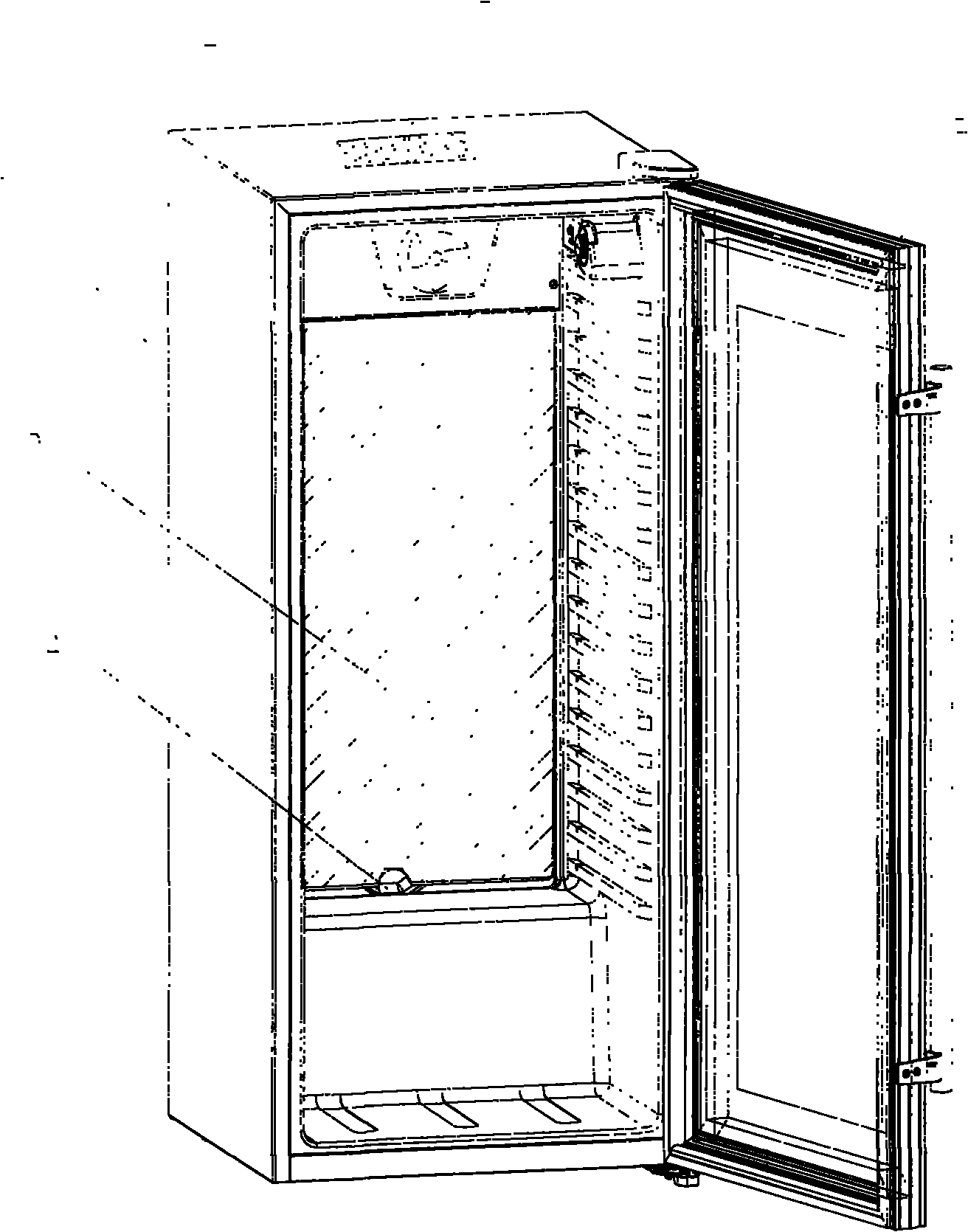
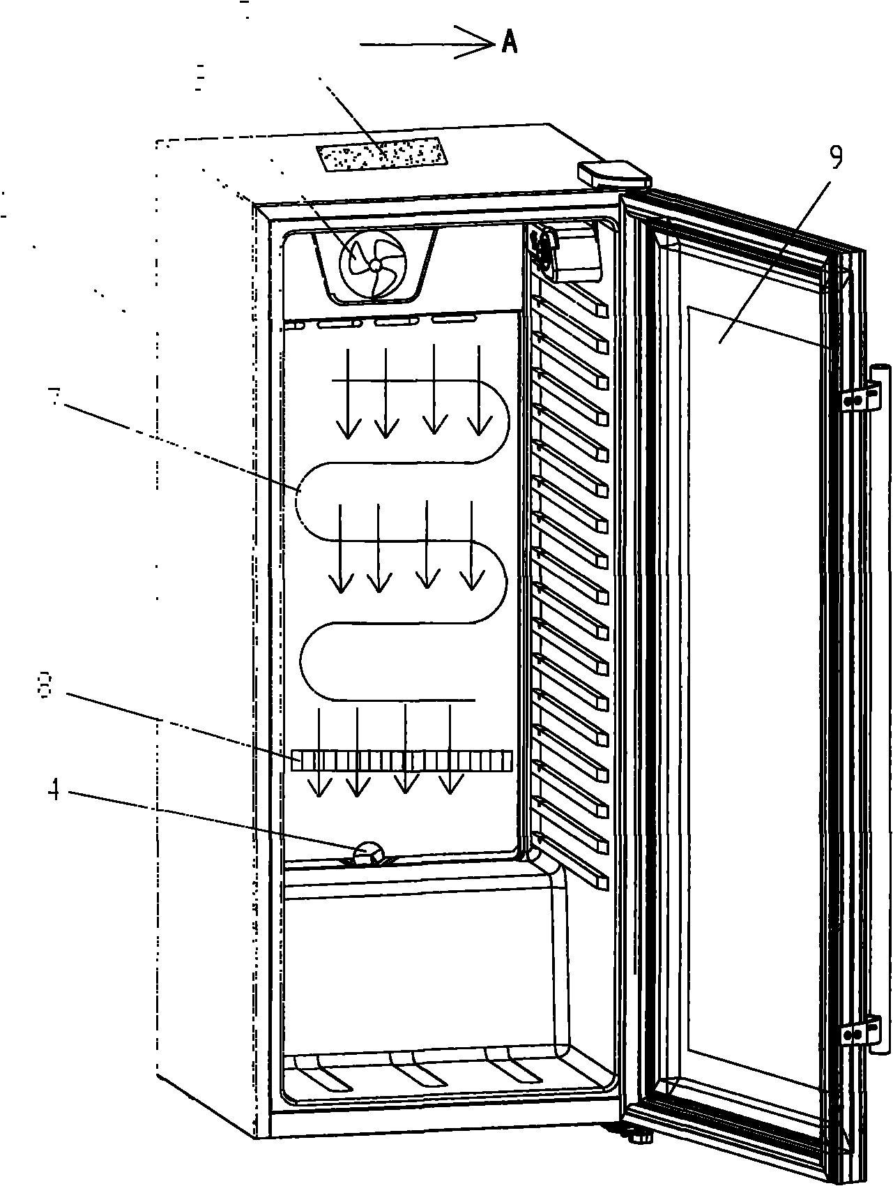
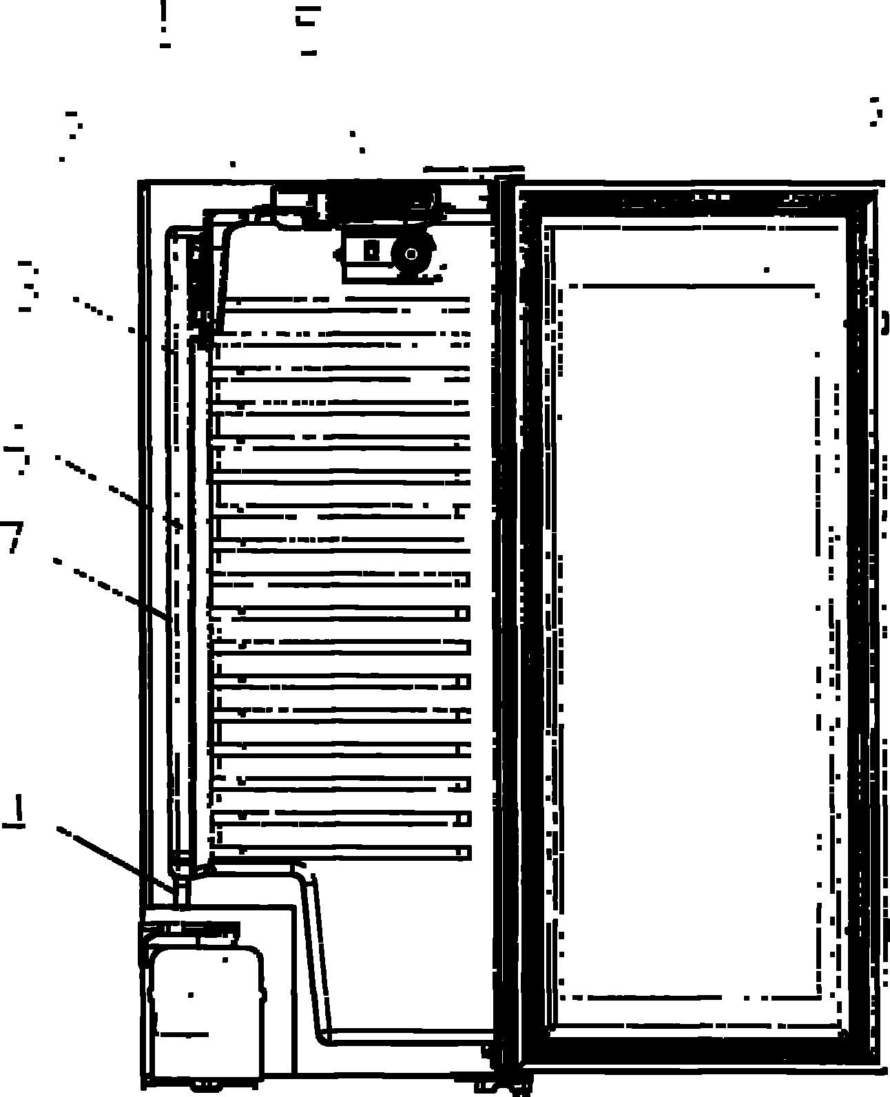
[0026] A constant humidity air-cooled wine cabinet, such as figure 2 , image 3 As shown, it includes a box body 1, a door body 9, a refrigeration unit, a humidifying fan 2, and a control unit 5. The refrigeration unit includes an evaporator 7 and a compressor. The box body 1 includes an evaporator cover 3 (evaporator cover 3). settings with figure 1 The setting of the air-cooled wine cooler in the prior art shown is the same, figure 2 It is the structural schematic diagram of the air-cooled wine cabinet of the present invention without the evaporator cover 3, the evaporator cover 3 is not shown), the evaporator cover 3 and the rear wall of the box 1 constitute an evaporator warehouse, and the evaporator 7 is arranged in In the evaporator compartment, an air inlet and an air outlet are arranged on the evaporator compartment; the humidifying fan 2 is arranged on the air inlet, and the air outlet faces the refrigerating area of ​​the wine cabinet (the setting of the air outl...


PUM


Abstract

The invention relates to a constant-humidity air-cooling wine cabinet which comprises a box body, a door body, a refrigeration unit, a humidification fan and a control unit, wherein the refrigeration unit comprises an evaporator and a compressor, the inside of the box body comprises a cover plate of the evaporator, an evaporator bin is formed between the cover plate of the evaporator and the back wall of the box body, the evaporator is arranged in the evaporator bin, an air inlet and an air outlet are arranged on the evaporator bin, the humidification fan is arranged on the air inlet or the air outlet, the air outlet faces to a cold storage area of the wine cabinet, the control end of the humidification fan of the control unit is connected with the humidification fan, and the refrigeration control end of the control unit is connected with the evaporator and the compressor; and a position below the evaporator in the evaporator bin, which corresponds to the air outlet, is provided with a humidification assembly. The invention also provides a microprocessor humidity control method of the constant-humidity air-cooling wine cabinet. At the stage of lower humidity of a refrigerating chamber when the compressor carries out the refrigeration operation, the circulation of air is quickened by utilizing the humidification fan, water on the humidification assembly is carried over, and the air in the refrigerating chamber is humidified, thereby enhancing the humidity control capability to the refrigerating chamber.

Description

technical field [0001] The invention relates to an air-cooled wine cooler, in particular to a constant-humidity air-cooled wine cooler and a microprocessor humidity control method for the constant-humidity air-cooled wine cooler. Background technique [0002] Due to its special purpose, the wine cabinet requires the best internal humidity to be about 65%. If the humidity is too high, the stored wine labels are prone to moisture, mold, damage, and falling off. The cork caps of wine are prone to moisture, swelling and mold. Metal bottle caps are easy to rust, and if the humidity is too low, the stored wine is easy to volatilize and deteriorate. figure 1 Shown is the internal structure diagram of the open door of the air-cooled wine cabinet in the prior art, including a box 1, a door 9, a refrigeration unit, a humidifying fan 2, and a control unit 5. The refrigeration unit includes an evaporator, a compressor, and a box 1. It includes an evaporator cover 3, an evaporator compa...

Claims


Application Information

Patent Timeline
Patent Type & Authority Applications(China)
IPC IPC(8): F25D31/00G05D22/02
Inventor 陶晓彦肖建军马战胜范志军
Owner HENAN XINFEI ELECTRICAL EQUIP
Why Eureka
Try Eureka