
Optical fiber microphone

A microphone and optical fiber technology, applied in the direction of sensors, electrical components, sensor components, etc., can solve the problems of no obvious increase in sensitivity and reduced volume, and achieve the effect of strong anti-electromagnetic interference and high sensitivity

Inactive Publication Date: 2010-07-14
BEIJING UNIV OF POSTS & TELECOMM
View PDF2 Cites 19 Cited by
  • Summary
  • Abstract
  • Description
  • Claims
  • Application Information

AI Technical Summary

Problems solved by technology

At present, the microphone based on MEMS technology is still a capacitance modulation type. The sound pressure causes the vibration of the MEMS diaphragm, and the diaphragm vibration causes the change of the capacitance value. Compared with the traditional condenser microphone, the sensitivity is not significantly improved, but the volume is reduced.

Method used


Image

  • Optical fiber microphone
  • Optical fiber microphone
  • Optical fiber microphone

Examples


Embodiment 1

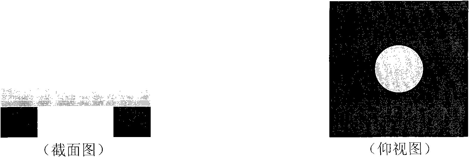
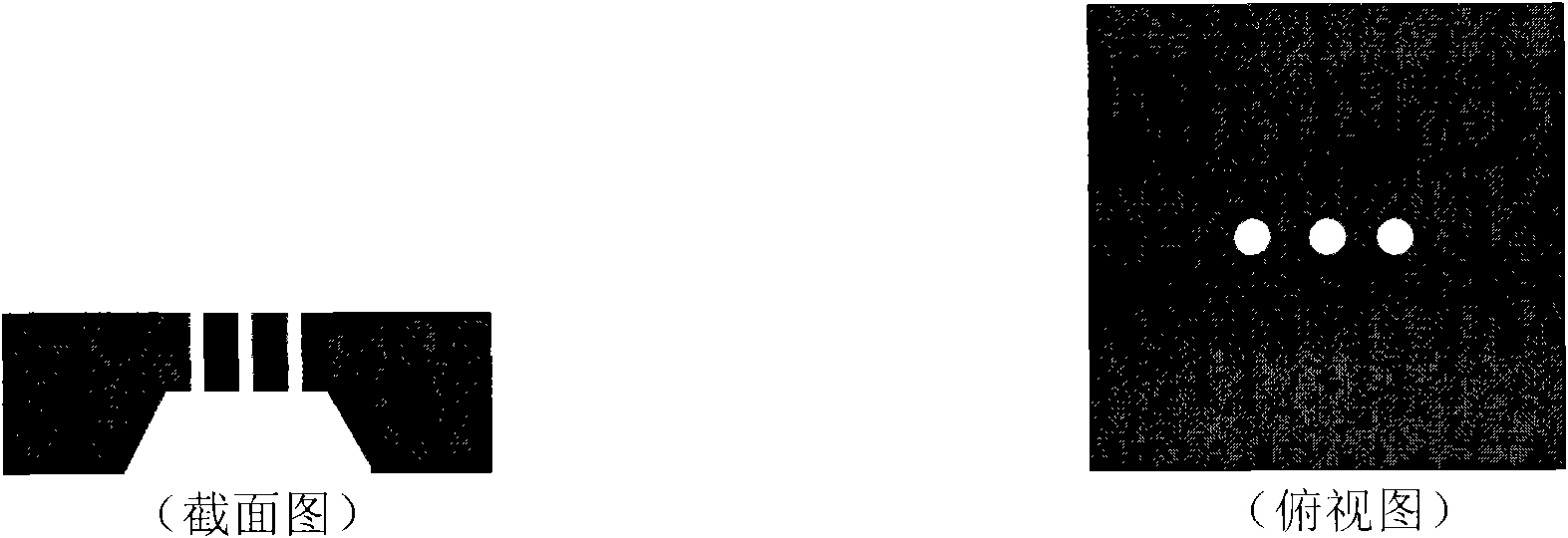
[0019] The invention provides a fiber optic microphone, such as Figure 4 As shown, the system includes an optical signal transmitting and receiving part 301 , a coupling unit 302 , a guiding fiber 303 and a fiber optic microphone probe 304 .

[0020] In this embodiment, the optical signal transmitting and receiving part 301 includes an optical signal generator 101 and a photoelectric conversion receiver 102 .

[0021] The optical signal generator 101 includes a light source part and a light source drive circuit part. The light source is an incoherent light source, which has a large emission angle. Generally, it is a light-emitting diode LED because of its simple structure and low price; it can also be replaced by a laser diode, a helium-neon laser, or a xenon arc lamp.

[0022] The part of the light source drive circuit is to ensure the stability of the emitted light intensity and low noise, because the stability and low noise of the light source are critical to the accurac...

Embodiment approach

[0034] The invention provides a fiber optic microphone, such as Figure 5 shown. The structure of the fiber optic microphone 2 is basically the same as that of the fiber optic microphone 1 in the first embodiment. The difference lies in: the material and thickness of the vibrating membrane 212 of the fiber optic microphone 2 are different, the vibrating membrane of the fiber optic microphone 2 is made of silicon dioxide, and its thickness is 2um. The Young's modulus of silicon dioxide is smaller than that of silicon nitride, so although the thickness increases, the Young's modulus is small, and the sensitivity can still be guaranteed. In addition, the number of vents 208 and sound inlets 206 of the fiber optic microphone can be changed, thereby changing the sensitivity of the microphone.


PUM


Abstract

The invention provides an optical fiber microphone structure, which comprises an optical signal transmitting and receiving part, a coupling unit, a guide optical fiber and a detector part of the optical fiber microphone. The detector part of the optical fiber microphone completes external modulation of a sound signal. The sound signal is transmitted to a detector by the optical fiber so as to accurately restore the sound signal. The MEMS technology is utilized to make the thickness of a film in the detector of the optical fiber microphone at the mum magnitude so as to greatly improve the sensitivity of the microphone. The design of the detector in the invention can also accurately position the distance between the optical fiber and the film so as to make the sensitivity of the microphone adjustable as required.

Description

technical field [0001] The invention relates to an optical fiber sensor, in particular to an optical fiber microphone. Background technique [0002] At present, microphones are widely used in people's lives, and it can be said that microphones are everywhere. However, the microphones in the prior art have shortcomings such as low sensitivity, electromagnetic interference, capacitive effect at low frequencies, and inability to work under harsh conditions (such as high temperature, toxic or corrosive chemical environments), which limit their use in special environments. Applications. [0003] The fiber optic acoustic sensor is a pressure sensor that can detect sound pressure, and the fiber optic pressure sensor is mainly divided into two types: intensity type and interference type. The intensity type fiber optic pressure sensor uses pressure to change the intensity of the detection light, so as to sense the size and change of pressure; Interferometric fiber optic pressure se...

Claims


Application Information

Patent Timeline
IPC IPC(8): H04R23/00
Inventor 洪小斌郭宏翔李博伍剑徐坤林金桐
Owner BEIJING UNIV OF POSTS & TELECOMM
Learn More