Supercharge Your Innovation With Domain-Expert AI Agents!

Light-emitting diode open-circuit-protection application specific integrated circuit

A light-emitting diode and open-circuit protection technology, which is applied in the direction of lamp circuit layout, protection for under-load or no-load response, light source, etc., can solve the problem of large cut-off leakage current and cut-off useless power consumption, turn-on voltage and turn-on useless work High power consumption, complex circuit and other problems, to achieve the effect of low cost, low conduction useless power consumption, and simple circuit structure

Inactive Publication Date: 2010-07-14
ANHUI QASKY QUANTUM SCI & TECH CO LTD
View PDF0 Cites 16 Cited by
  • Summary
  • Abstract
  • Description
  • Claims
  • Application Information

AI Technical Summary

Problems solved by technology

One is that the cut-off leakage current and cut-off useless power consumption are relatively large, the second is that the turn-on voltage and turn-on useless power consumption are relatively large, and the third is that the circuit is more complicated and the cost is high

Method used


Image

  • Light-emitting diode open-circuit-protection application specific integrated circuit
  • Light-emitting diode open-circuit-protection application specific integrated circuit
  • Light-emitting diode open-circuit-protection application specific integrated circuit

Examples


Embodiment 1

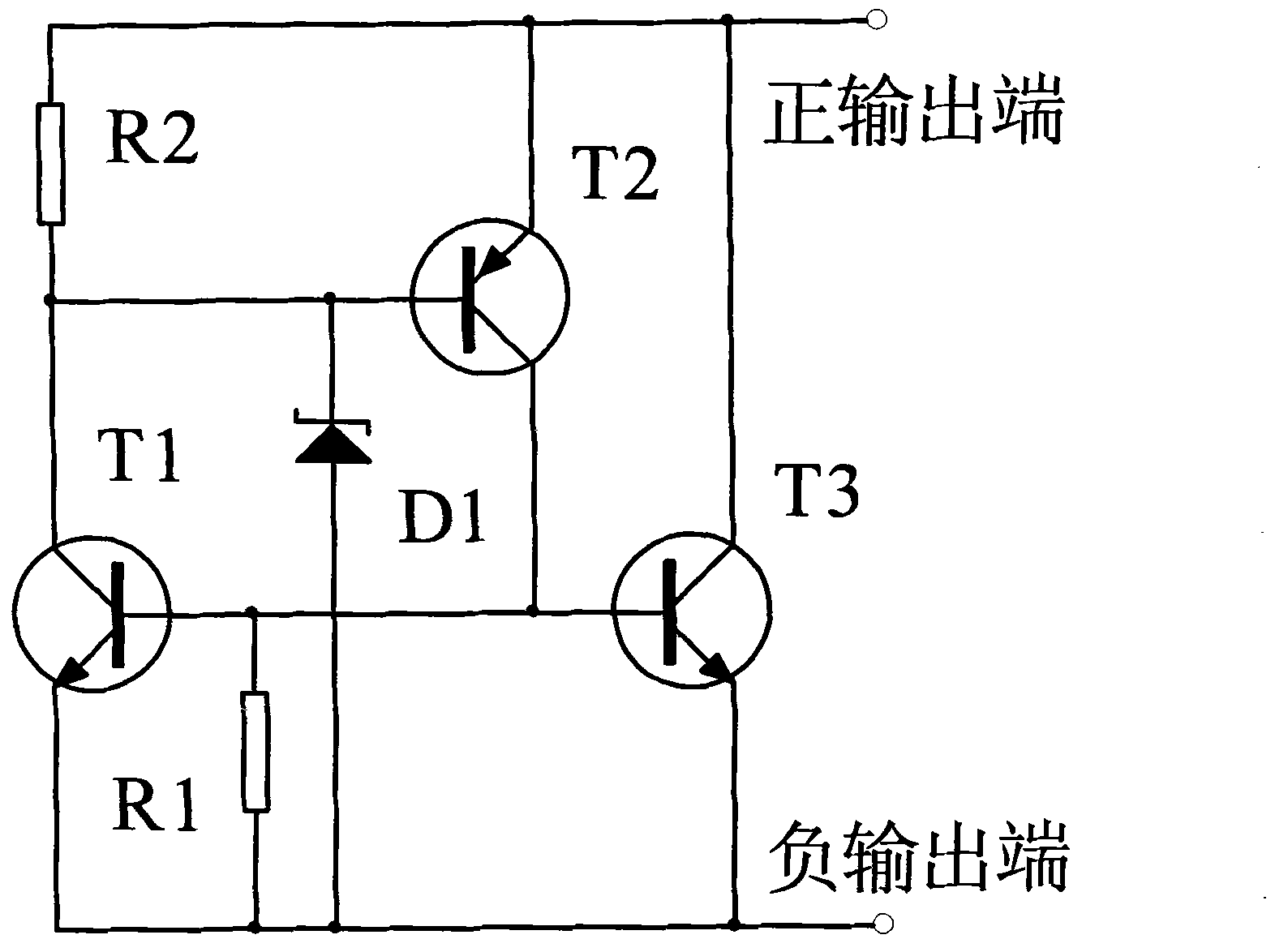
[0016] The basic principle of the present invention is: use an NPN transistor and a PNP transistor to form a blocking circuit, and use the reverse breakdown voltage of the Zener diode plus the base-to-emitter forward conduction voltage of the NPN transistor as the blocking circuit The threshold voltage and the detection voltage for judging the open state of the light-emitting diodes are used to bias the bases of the NPN transistor and the PNP transistor that constitute the blocking circuit with zero bias to prevent false reversal of the blocking circuit.

[0017] like figure 1 As shown, a light-emitting diode open-circuit protection special integrated circuit, its internal circuit diagram includes: resistor R1, low-power NPN transistor T1, resistor R2, low-power horizontal PNP transistor T2, Zener diode D1 and medium-power NPN transistor T3, one end of R1 is connected to the emitter of T1 and the emitter of T3 as a negative output end, one end of R2 is connected to the emitter...

Embodiment 2

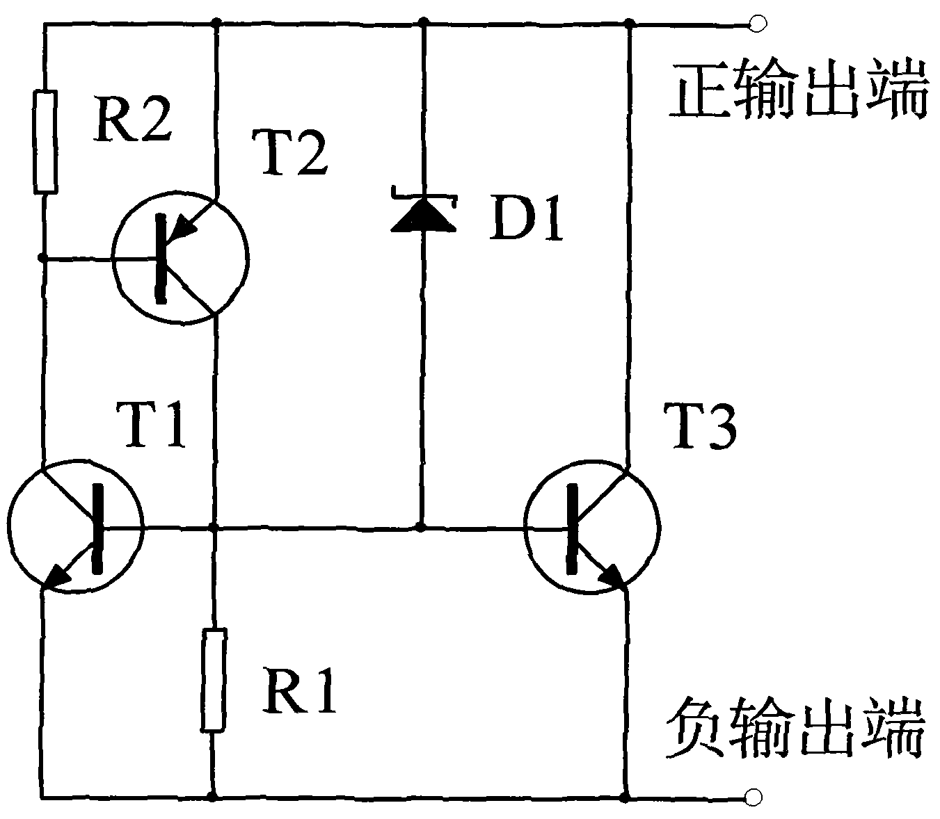
[0020] The basic principle of the present invention is: use an NPN transistor and a PNP transistor to form a blocking circuit, and use the reverse breakdown voltage of the Zener diode plus the base-to-emitter forward conduction voltage of the PNP transistor as the blocking circuit The threshold voltage and the detection voltage for judging the open circuit state of the light-emitting diode are respectively used to bias the bases of the NPN transistor and the PNP transistor that constitute the blocking circuit with zero bias to prevent false reversal of the blocking circuit.

[0021] like figure 2 As shown, a light-emitting diode open-circuit protection special integrated circuit, its internal circuit diagram includes: resistor R1, low-power NPN transistor T1, resistor R2, low-power horizontal PNP transistor T2, Zener diode D1 and medium-power NPN transistor T3, one end of R1 is connected to the emitter of T1, the emitter of T3 and the positive pole of D1 as a negative output ...


PUM


Abstract

The invention relates to a light-emitting diode open-circuit-protection application specific integrated circuit. The internal circuit comprises resistors R1 and R2, a Zener diode D1, NPN crystal triodes T1 and T3 and a PNP crystal triode T2, wherein one end of R1 is connected with the emitter of T1 and the emitter of T3 and used as the negative output end; one end of R2 is connected with the emitter of T2, the negative electrode of D1 and the collector of T3 and used as the positive output end; the other end of R1 is connected with the base of T1, the collector of T2, the positive electrode of D1 and the base of T3; and the other end of R2 is connected with the collector of T1 and the base of T2. In application, the positive output end and the negative output end are respectively connected with the positive end and the negative end of an external light-emitting diode. The application specific integrated circuit has the advantages of simple structure, low power consumption, low drain current and low manufacturing cost.

Description

technical field [0001] The invention belongs to the field of integrated circuits, and in particular relates to a dedicated integrated circuit for open-circuit protection of light-emitting diodes. Background technique [0002] As a new generation of semiconductor light-emitting devices, LEDs have the characteristics of high light efficiency, long life, environmental protection and energy saving. High-power light-emitting diodes continue to replace existing lighting technologies such as sodium lamps and mercury lamps, and are widely used in urban street lights, tunnel lights, landscape lighting Lamps and interior lighting etc. In the application of LED lighting and LED backlight, it is often necessary to connect multiple LEDs in series to simplify the circuit, reduce the cost, and improve the constant current driving precision and circuit efficiency. However, when any one LED is damaged and opened, the entire LED string will fail. The open-circuit fault of light-emitting dio...

Claims


Application Information

Patent Timeline
IPC IPC(8): H05B37/00H02H3/12
Inventor 赵义博
Owner ANHUI QASKY QUANTUM SCI & TECH CO LTD
Features
  • R&D
  • Intellectual Property
  • Life Sciences
  • Materials
  • Tech Scout
  • Unparalleled Data Quality
  • Higher Quality Content
  • 60% Fewer Hallucinations
Learn More