Process for producing tube member made of fiber-reinforced resin

A fiber-reinforced resin and manufacturing method technology, applied in vehicle parts, control devices, household components, etc., can solve the problems of fiber orientation disorder, simultaneous curing, and no disclosure.

Inactive Publication Date: 2010-07-14
TOYOTA JIDOSHA KK +1
View PDF1 Cites 9 Cited by
  • Summary
  • Abstract
  • Description
  • Claims
  • Application Information

AI Technical Summary

Problems solved by technology

[0007] According to the above-mentioned assembly method, when the fiber layer is folded back, the orientation of the fiber is disturbed, and there is a serious problem that the initial bending strength cannot be exhibited due to the excellent bending moment at the end.
In addition, there is also a problem that uncured resin adheres to the metal mold mandrel, and when it is thermally cured, it is cured to the mandrel at the same time.
Regarding the connection method between the torque transmission connector and the fiber-reinforced plastic tubular member in the propeller shaft disclosed in the above-mentioned Patent Document 1, the above-mentioned problem is not disclosed at all, and there is no description about the solution.

Method used


Image

  • Process for producing tube member made of fiber-reinforced resin
  • Process for producing tube member made of fiber-reinforced resin
  • Process for producing tube member made of fiber-reinforced resin

Examples


Embodiment Construction

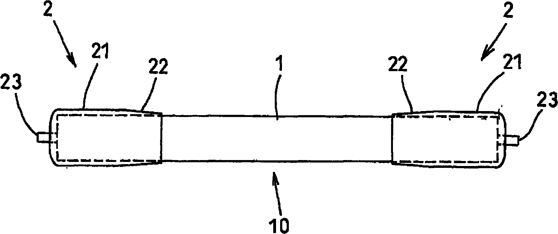
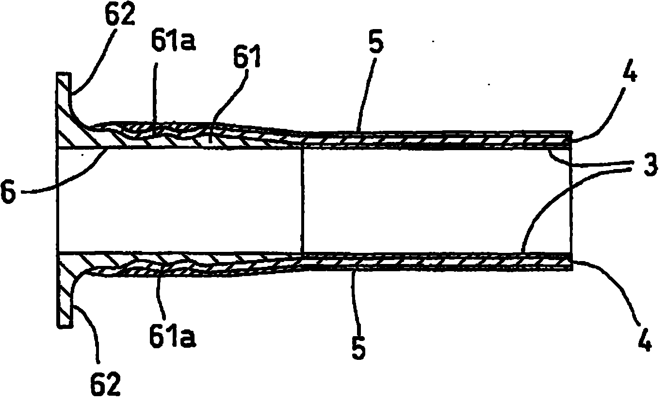
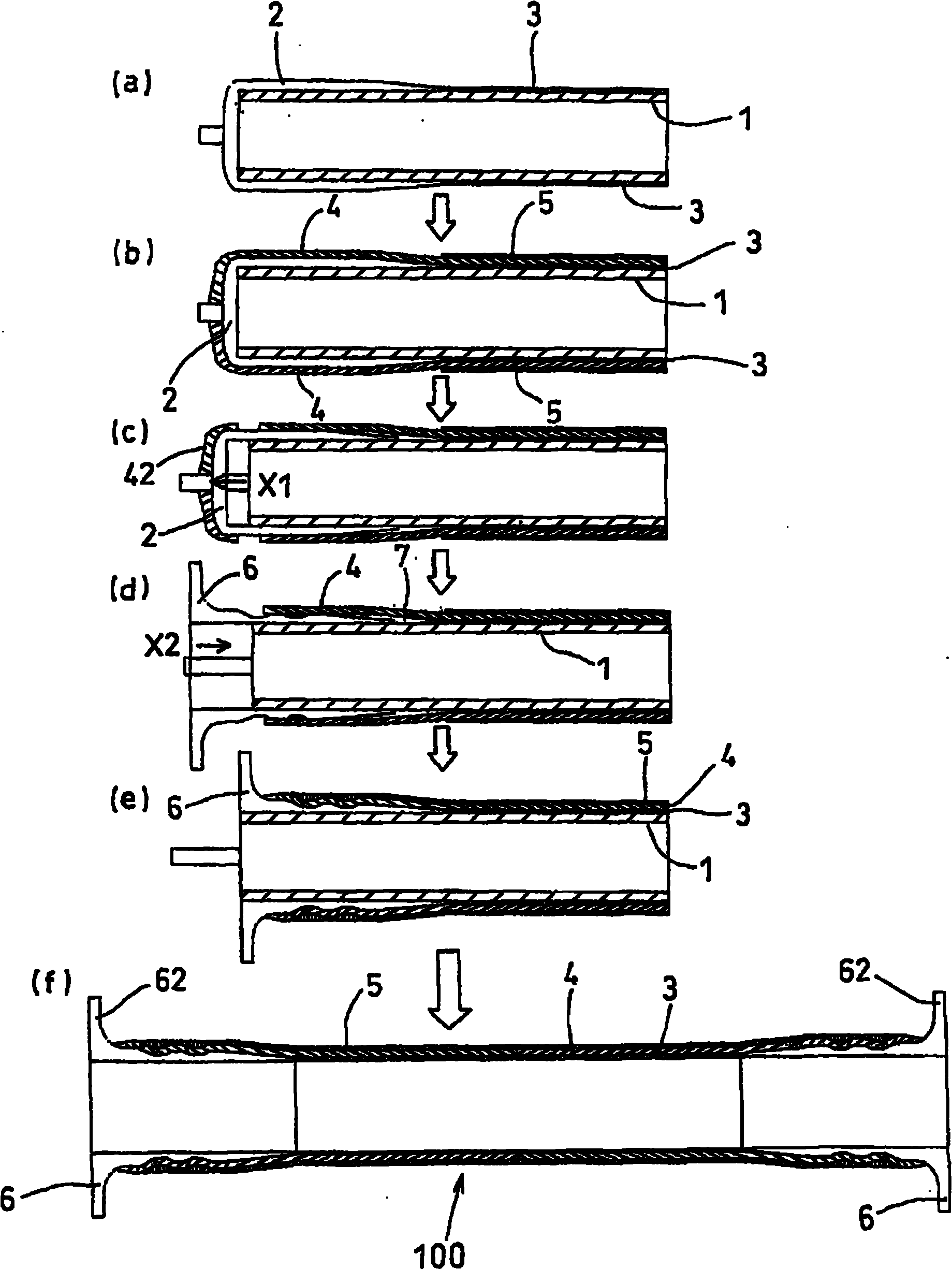
[0047] Hereinafter, embodiments of the present invention will be described with reference to the drawings. figure 1 is the front view of the base material including mandrel and end mounting material, figure 2 is a sectional view illustrating the end structure of the torque tube, image 3 (a) to (f) are flowcharts sequentially explaining the production method of the present invention. Figure 4 is description image 3 a perspective view of (a), Figure 5 , Figure 6 is explained in turn image 3 (b) Perspective view. Figure 7 It is a figure explaining the situation of inserting the reinforcing member into the end of the member, Figure 8 It is a cross-sectional view illustrating the end structure of the reinforced torque tube. In addition, the illustration of the bearing and the shaft inside the torque tube is omitted.

[0048] figure 1 A mold for manufacturing a torque tube as a carbon fiber-reinforced resin tube member is shown. The mold base 10 is composed of a l...


PUM


Abstract

A process for producing a tube member made of fiber-reinforced resin, in which without the need to fold back an end portion of a fiber layer impregnated with an uncured resin, while maintaining a fiber orientation at an initial orientation posture, a tube member of resin fiber and a flanged tube material permitting direct rigid bonding to an engine box, etc. can be bonded together through extremely easy procedure. In the process, a base material (10) consisting of a mandrel (1) and, fitted to one end thereof, an end-fitted material (2) having an expanded-diameter portion with diameter expanded as compared with that of the mandrel and a projection is provided. A first winding layer (3) is formed by hoop winding of a fiber impregnated with an uncured resin around the outer circumference of the mandrel (1). Further, a second winding layer (4) is formed by helical winding of a fiber around the outer circumference thereof. An end portion of the second winding layer (4) is cut, and the end portion and the end-fitted material (2) are cut off from the mandrel (1) to thereby form an insertion space (7). A flanged tube material (6) is inserted in the insertion space (7). A third winding layer (5) is formed by hoop winding of a fiber around the outer circumference of the second winding layer (4), followed by heating treatment.

Description

technical field [0001] The present invention relates to a method for manufacturing a tubular member made of fiber-reinforced resin, especially a tubular member used as a torque tube of a vehicle, from a mandrel and uncured resin impregnated with fibers. Background technique [0002] In a vehicle equipped with a front engine and a transmission (transmission) and a differential (transaxle) on the rear side of the vehicle, the drive is transmitted from the front engine to the transmission. As a structural member, a cylindrical torque tube is used in which a drive shaft (input shaft) passes through and a bearing for supporting the drive shaft is built in. [0003] One end of the torque tube is rigidly combined with the engine case by bolts and the like, and the other end is also rigidly combined with the transmission device by bolts and the like. Since the long part involved is a structure in which both ends are rigidly coupled to the drive system, the torque tube is particular...

Claims


Application Information

Patent Timeline
Patent Type & Authority Applications(China)
IPC IPC(8): B29C70/16B60K17/22B29K101/10B29K105/08B29L23/00
CPCB29L2031/75B29D23/001B29C53/585B29C70/86B60K17/22B29L2031/24B29C70/545B29C70/32B29C37/0082B29K2705/00
Inventor 小崎高裕野々垣保纪高岛翼
Owner TOYOTA JIDOSHA KK
Why Eureka
Try Eureka