Novel fiber grating pressure transducer

A pressure sensor and fiber grating technology, applied in the field of fiber grating pressure sensors, can solve the problems of fiber grating pressure and temperature cross-sensitivity, and achieve the effects of low signal transmission loss, good safety, and avoiding the problem of measurement signal cross-sensitivity.

Inactive Publication Date: 2010-07-21
NORTHEASTERN UNIV
View PDF0 Cites 7 Cited by
  • Summary
  • Abstract
  • Description
  • Claims
  • Application Information

AI Technical Summary

Problems solved by technology

[0004] The purpose of the present invention is not only to overcome the deficiencies of the prior art, to realize the detect

Method used


Image

  • Novel fiber grating pressure transducer
  • Novel fiber grating pressure transducer
  • Novel fiber grating pressure transducer

Examples


Embodiment Construction

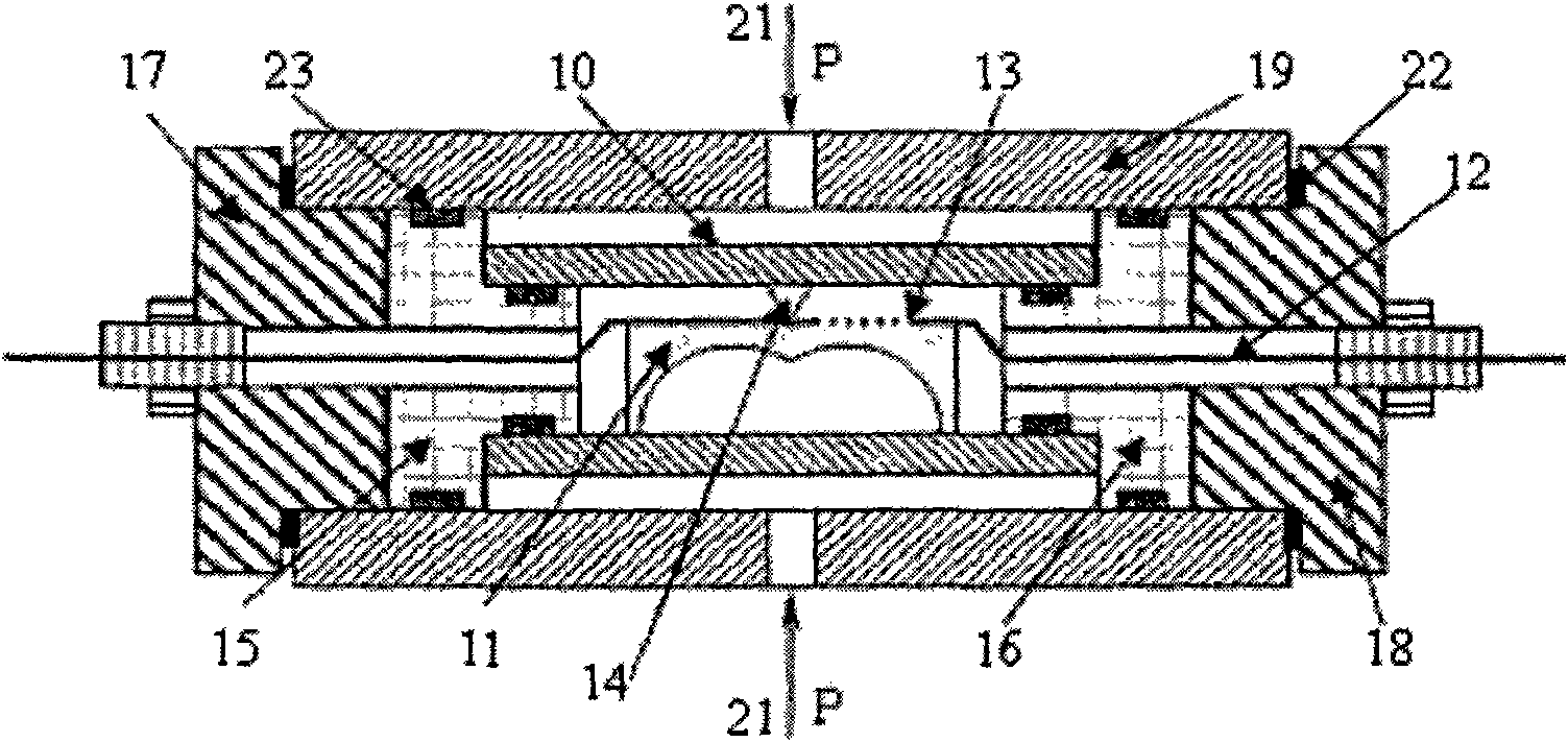
[0020] The fiber grating pressure sensor structure and its measurement principle proposed by the present invention are described as follows in conjunction with the accompanying drawings:

[0021] figure 1 A schematic diagram of the sensor structure. The free elastic cylinder 10 that directly feels the external pressure is "actively" fixed inside the outer protective shell 19 through two end elements 15 and 16 of the same structure and threaded closure elements 17 and 18, and the end elements are connected with the elastic cylinder, The end face element and the outer casing are closely connected by a gasket 22 and an annular sealing ring 23. The cantilever beam 11 is placed inside the free elastic cylinder and maintains permanent "active" contact with it through the contact point 14, engraved on the optical fiber The fiber grating 13 on 12 is fixed on the position between the center of the upper surface of the cantilever beam and the right end, and is connected with the extern...


PUM

PropertyMeasurementUnit
Lengthaaaaaaaaaa

Abstract

The invention discloses a novel fiber grating pressure transducer. A fiber grating is fixedly connected to the upper surface of a double-arc uniform-thickness cantilever; the cantilever is arranged inside a free elastic cylinder and keeps permanent active contact with the free elastic cylinder through contact points; the elastic cylinder is fixed at proper position inside a protective shell through two end head elements and sealing elements; and the elements are mutually connected by a certain pretightening force by using sealing pads (among end head planes) or placing in annular sealing rings (among cylindrical surfaces) in grooves. By adopting a method for detecting the fiber grating reflectance spectrum 3dB band width, the invention can avoid the problem that the temperature influences a measuring signal. The invention has the advantages that the measurement of higher pressure can be realized; signal transmission has low loss and no distorsion, so the invention is applicable to measurement for a long distance; and a sensor probe part of the system has electric insulation, good safety and the like.

Description

technical field [0001] The invention relates to a fiber grating pressure sensor, which belongs to the technical field of sensors and detection. Background technique [0002] At present, there are many researches and products on pressure detection at home and abroad, and the traditional electrical measurement method is often used. This method not only has the disadvantages of poor anti-electromagnetic interference ability and low sensitivity, but also is not suitable for long-distance sensing and Signal transmission. The optical fiber pressure detection method provides a better solution. [0003] In terms of optical fiber pressure detection technology, (Tomasz R.Woli'nski, Aleksandra Jarmolik, and Wojtek J.Bock, Development of Fiber Optic Liquid Crystal Sensor for Pressure Measurement.IEEETRANSACTIONS ON INSTRUMENTATION AND MEASUREMENT, 48(1), 1999) proposed " The liquid crystal + high birefringence polarization-maintaining optical fiber pressure sensor" method, based on th...

Claims


Application Information

Patent Timeline
IPC IPC(8): G01L1/24G01L11/02
Inventor 赵勇张馨元
Owner NORTHEASTERN UNIV
Why Eureka
Try Eureka