High-precision local wireless positioning system

A wireless positioning system and high-precision technology, applied in radio wave measurement systems, positioning, measuring devices, etc., can solve the problems of complex antenna array structure, low accuracy, short propagation time, etc., to suppress white noise interference and ensure positioning accuracy. , the effect of increasing system capacity

Inactive Publication Date: 2010-07-21
SOUTHEAST UNIV
View PDF0 Cites 21 Cited by
  • Summary
  • Abstract
  • Description
  • Claims
  • Application Information

AI Technical Summary

Problems solved by technology

The above positioning systems have their own defects. For example, the TOA and TDOA schemes need to measure the arrival time of the signal, but because the wireless signal propagates at the speed of light in the air, the propagation time is short in a local area, and it is difficult to measure directly; TOA using UWB technology The scheme has high precision, but the wireless propagation distance is about 10 meters, and its application is limited; the AOA scheme requires a complex antenna array structure, which is not suitable for local positioning applications; the RSSI scheme has a simple structure, but is greatly affected by noise and has low precision; Interferometric positioning has high accuracy, but the positioning time is long, and it is only suitable for stationary nodes
To sum up, there is currently no wireless positioning system that can achieve high-precision positioning within a local area (100-meter radius)

Method used


Image

  • High-precision local wireless positioning system
  • High-precision local wireless positioning system
  • High-precision local wireless positioning system

Examples


Embodiment Construction

[0035] The present invention will be further described below in conjunction with the accompanying drawings.

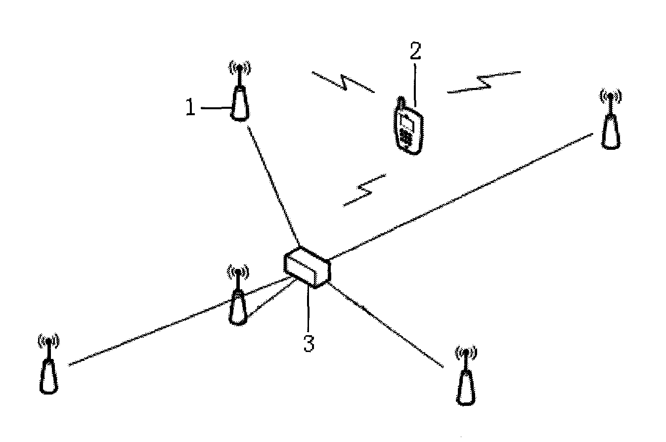
[0036] Such as figure 1 As shown, a high-precision local wireless positioning system of the present invention includes an anchor node 1, a positioned target node 2, and a central processing module 3. The anchor node 1 includes an apex anchor node and a central anchor node, and the apex anchor node is deployed near the target node. On the vertices of the polygon at the edge of the positioning area, the central anchor node is close to the central processing module 3 deployed at the center of the polygon, and each anchor node 1 is connected to the central processing module 3 respectively. In this system, five positioning anchor nodes are placed in the center of the plane to be positioned, four of which are placed at the four vertices of the square, and the other anchor node is placed at the center of the square, and the vertex anchor nodes are placed as close as possible ...


PUM


Abstract

The invention discloses a high-precision local wireless positioning system which comprises anchor nodes, a positioned destination node and a central processing module, wherein the anchor nodes comprise a vertex anchor node and a central anchor node, the vertex anchor node is allocated on the vertex of a polygon on the edge of a positioned region, the central anchor node is abutted against the central processing module arranged at the center of the polygon, and each anchor node is respectively connected with the central processing module; the positioned destination node is in a sleep state in normal times, and when the node needs to be positioned, the positioned destination node is aroused, emits a wireless signal which is modulated through an ASK (Amplitude Shift Keying) modulator, and then continues to sleep until being aroused the next time; and a plurality of groups of arrival time differences are obtained through the demodulation and phase discrimination processing of the anchor modes on the wireless signal and the relevant operation based on a received signal phase difference, and then the position of the positioned node is determined according to the position relation between the anchor nodes. The invention can realize the high-precision positioning within a local range (100-meter radius), and the power consumption of the positioned destination node is low.

Description

technical field [0001] The invention relates to a local wireless positioning system, in particular to a high-precision local wireless positioning system capable of realizing high-precision positioning within a local range (100-meter radius) and having low power consumption of a positioned target node. Background technique [0002] At present, wireless positioning systems are widely used in industrial automation, military target positioning, logistics asset tracking, underground positioning, and dangerous environment target tracking. [0003] The existing local positioning systems are: based on time of arrival (TOA), based on time difference of arrival (TDOA), based on angle of arrival (AOA), based on signal strength (RSSI) and interferometric positioning systems. The above positioning systems have their own defects. For example, the TOA and TDOA schemes need to measure the arrival time of the signal, but because the wireless signal propagates at the speed of light in the air...

Claims


Application Information

Patent Timeline
Patent Type & Authority Applications(China)
IPC IPC(8): G01S5/02G01S5/06
Inventor 胡爱群王侃磊张倩
Owner SOUTHEAST UNIV
Why Eureka
Try Eureka