SMD power inductor and manufacturing method thereof

A power inductor, chip technology, applied in the direction of inductor/transformer/magnet manufacturing, transformer/inductor coil/winding/connection, inductor with magnetic core, etc., can solve the problems of poor electrical performance and low manufacturing efficiency , to improve production efficiency, ensure consistency, and reduce the number of turns

Inactive Publication Date: 2010-07-21
深圳感通科技有限公司
View PDF0 Cites 15 Cited by
  • Summary
  • Abstract
  • Description
  • Claims
  • Application Information

AI Technical Summary

Problems solved by technology

[0004] One of the technical problems to be solved by the present invention is to provide a patch type power inductor for the defects of poor electrical performance and low manufacturing efficiency of the above-mentioned inductors in the prior art

Method used


Image

  • SMD power inductor and manufacturing method thereof
  • SMD power inductor and manufacturing method thereof
  • SMD power inductor and manufacturing method thereof

Examples


Embodiment Construction

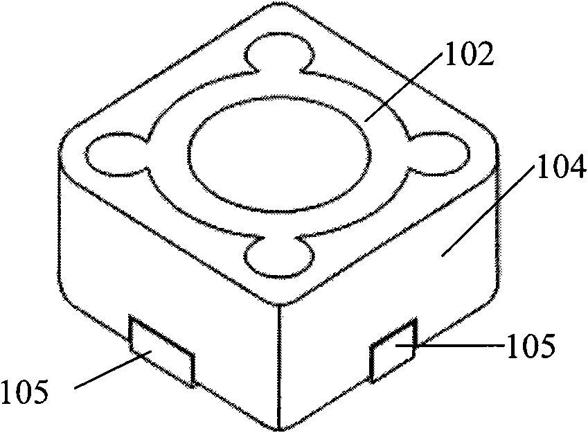
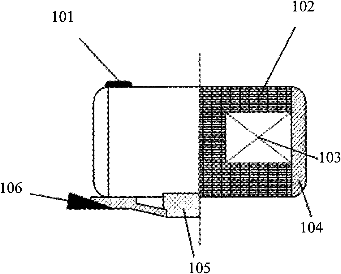
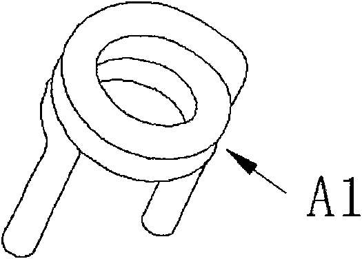
[0050] The patch type power inductor of the present invention includes a magnetizer and an enameled wire coil, wherein the coil includes a main body and an extension part, the magnetizer and the coil are integrally formed, and the material constituting the magnetizer is tightly filled in the The inside of the coil main body is tightly wrapped on the outside of the coil main body; the extension of the coil protrudes out of the magnetic conductor to form the electrodes of the inductor, and the electrodes are welded with the magnetic conductor. Electrode end piece. Preferably, the extension part is a flat structure, protrudes from opposite side surfaces of the magnetic conductor respectively, and is respectively bent to be close to the bottom surface of the magnetic conductor. The detailed manufacturing process and product structure are detailed below.

[0051] 1. Preparation of magnetic conductor powder

[0052] Among the present invention, the magnetizer mainly consists of two ...


PUM


Abstract

The invention relates to an SMD power inductor, which comprises a magnetizer and an enamelled wire coil, wherein the coil comprises a main body and an extension part; the magnetizer and the coil are integrated into an integral structure; a material for preparing the magnetizer is tightly filled in the main body and is tightly coated outside the main body; the extension part extends out of the magnetizer to form an electrode of the inductor; and an electrode tip attached to the magnetizer is welded on the electrode. The invention also relates to a method for manufacturing the SMD power inductor, which comprises the following steps: preparing the coil and powder for preparing the magnetizer; diecasting the coil and the powder; and welding the electrode tip on the electrode of the coil. The SMD power inductor and the manufacturing method thereof have the advantages of good electric property of the inductor, high production efficiency and good consistency of product performance.

Description

technical field [0001] The present invention relates to wire-wound inductors, more specifically, to a chip-type power inductor and a manufacturing method thereof. Background technique [0002] The main components of the existing SMD power inductors are coils and magnetic conductors, where the magnetic conductors can be magnetic cores, iron cores or copper cores. Such as figure 1 and figure 2 As shown, in the existing SMD power inductor products, the shape of the magnetic conductor 102 is usually cylindrical, I-shaped (such as figure 2 ), ring, etc.; the enameled wire 103 is wound on the outside of the magnetic conductor 102 to form a coil, and then the magnetic ring 104 is bonded to the magnetic conductor 102 with glue 101, and then the electrode 105 and the electrode end piece 106 are welded on the magnetic conductor 102 , and finally form a cylindrical SMD power inductor and an I-shaped SMD power inductor (such as figure 1 and figure 2 ), and an annular chip power ...

Claims


Application Information

Patent Timeline
Patent Type & Authority Applications(China)
IPC IPC(8): H01F17/04H01F27/28H01F27/29H01F41/00B22F1/00
Inventor 王向群
Owner 深圳感通科技有限公司
Why Eureka
Try Eureka