Method for allocating dynamic bandwidth of ether passive optical network

An optical fiber network, passive technology, applied in the field of dynamic bandwidth assignment, can solve the problems of increasing the polling time, reducing the completion transmission rate, poor bandwidth utilization rate, etc., so as to improve the bandwidth utilization efficiency and reduce the packet loss rate. , the effect of improving the transmission efficiency

Inactive Publication Date: 2012-05-23
CHUNGHWA TELECOM CO LTD
View PDF0 Cites 0 Cited by
  • Summary
  • Abstract
  • Description
  • Claims
  • Application Information

AI Technical Summary

Problems solved by technology

[0002] There have been many studies on the scheduling of the upstream signal of the Ethernet passive optical fiber network. Since the upstream bandwidth of the optical terminal unit is shared and shared, how to allocate the upstream bandwidth of the optical terminal unit has become an important issue; and the earliest proposed upstream The signal scheduling method is Time Division Multiple Access (TDMA) (such as reference [1]), and each optical terminal unit is assigned a fixed bandwidth (timeslot). Although the time division multiple access method is used in practical systems It is easier to design, but it cannot cope with the variable data packet demand of the optical terminal unit, which leads to poor bandwidth utilization; therefore, in order to cope with the bursty traffic demand of data services, Kramer (such as reference [2] ) proposed a polling mechanism with adjustable interleaved polling time (Interleaved Polling with Adaptive Cycle Time, IPACT), which improved the dynamic bandwidth requirements of optical terminal units, and this method was also referred to the IEEE802.3ah committee as an Ethernet The standard proposal of MultiPoint Control Protocol (MPCP) for passive fiber optic networks, however, the adjustable plug-in polling time has requirements for the quality of service of various services of optical terminal units, such as delay (delay) and packet discard probability (drop probability) is not taken into account;
[0003] According to the adjustable plug-in polling time rule, the packets of the optical terminal unit adopt the first-in-first-out (First Come First Serve, FCFS) principle, so all packets will have a certain delay time, and for voice and real-time video services , is unable to tolerate delay, or large delay variation (jitter); therefore, many studies have proposed a scheduling mechanism to improve service quality: for example, reference [3] proposes a high-priority dynamic bandwidth assignment rule (DBA-High Priority ), for high-priority services, reduce the packet delay time and delay variation, but at the same time sacrifice the discard rate of low-priority packets (to increase the discard rate), delay time (to lengthen the delay), and reduce the completion rate (throughput ), resulting in unfairness; in addition, references [4], [5] proposed the two-layer bandwidth allocation rule for optical terminal units (intra-ONU, inter-ONU, two layer bandwidth allocation, TLBA), the main method is to enlarge The polling times for various classes of traffic per OTU try to resolve the unfairness of high- and low-priority packets in Ref. [3]; but thus increase the delay time and reduce the completion of high-priority services Transmission rate, the main problem of this law is that it cannot meet the characteristics of burst traffic;
[0004] However, the Burst-polling based delta DBA (Burst-polling based delta DBA) rule (reference [6]) and the multiple service dynamic bandwidth assignment (DBA with multiple service, DBAM) rule (such as reference [7] ]) proposed a classification service traffic method for predicting possible future arrivals, trying to improve the average packet delay time, but it uses the concept of a single maximum bandwidth (maximum window). One piece; the optical main control terminal gives more bandwidth to the optical terminal unit, which causes a waste of bandwidth and reduces transmission efficiency

Method used


Image

  • Method for allocating dynamic bandwidth of ether passive optical network
  • Method for allocating dynamic bandwidth of ether passive optical network
  • Method for allocating dynamic bandwidth of ether passive optical network

Examples


Embodiment

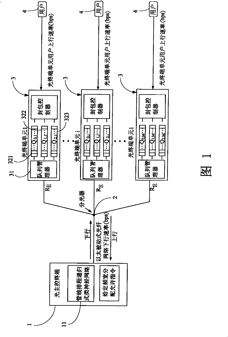
[0042] see figure 1 , is the Ethernet passive optical fiber network system architecture diagram of the dynamic bandwidth assignment method of the Ethernet passive optical fiber network of the present invention, which includes:

[0043] The optical main control terminal 1 is connected with the optical splitter 2, and the downlink packet is broadcast to several optical terminal units 3 through the optical splitter 2. In addition, the optical main control terminal 1 has a pipeline scheduling recursive neural network 11, Allocate permission commands with a given bandwidth;

[0044] The optical splitter 2 is connected with the optical main control terminal 1 and several optical terminal units 3, and is a single-point to multi-point optical splitter (splitter);

[0045] Several optical terminal units 3 are connected to the optical splitter 2 and several clients 4, and each optical terminal unit receives its own packets according to its Logic Link Identifier (LLID), and discards oth...


PUM


Abstract

The invention discloses a method for allocating the dynamic bandwidth of an ether passive optical network, which comprises a predictor and a dynamic bandwidth allocation rule (PQ-DBA algorithms) capable of upgrading and adjusting the service quality. The predictor is mainly used for predicting the action of terminal users and the packing quantity of various services with a line pipe scheduling predictor formed by recursion type artificial neural network and an extension recursion least square method learning rule. The method builds better service quality traffic guarantee with the bandwidth which is allocated by an original light terminal unit according to an optic main control terminal and the user packets which are transmitted from the high priority to the low priority.

Description

technical field [0001] The invention relates to a dynamic bandwidth assignment method of an Ethernet passive optical fiber network, in particular to a pipeline scheduling predictor (PRNN) composed of a recursive neural network, and an extended recursive least square method (ERLS) learning law. Background technique [0002] There have been many studies on the scheduling of the upstream signal of the Ethernet passive optical fiber network. Since the upstream bandwidth of the optical terminal unit is shared and shared, how to allocate the upstream bandwidth of the optical terminal unit has become an important issue; and the earliest proposed upstream The signal scheduling method is Time Division Multiple Access (TDMA) (such as reference [1]), and each optical terminal unit is assigned a fixed bandwidth (timeslot). Although the time division multiple access method is used in practical systems It is easier to design, but it cannot cope with the variable data packet demand of the...

Claims


Application Information

Patent Timeline
Patent Type & Authority Patents(China)
IPC IPC(8): H04L12/56H04Q11/00H04L47/80
Inventor 彭正文吴星毅张仲儒
Owner CHUNGHWA TELECOM CO LTD
Why Eureka
Try Eureka