Prefabricated vertical member

A component, vertical technology, applied in building components, building structures, columns, etc., can solve problems such as low construction efficiency, long construction period, and large amount of work at heights, to ensure worker safety, construction efficiency and construction quality improvement Effect

Inactive Publication Date: 2010-07-28
管乃彦
View PDF3 Cites 35 Cited by
  • Summary
  • Abstract
  • Description
  • Claims
  • Application Information

AI Technical Summary

Problems solved by technology

[0002] With the acceleration of China's urbanization process, the society's demand for high-rise residences is becoming increasingly urgent. Traditional buildings are constructed on site (including steel bar binding, formwork support, concrete pouring, etc.). The technical level is uneven, and the amount of high-altitude operations is large. There are problems such as large consumption of formwork and support materials, low construction efficiency, long construction period, and difficult control of project quality.
However, the existing prefabricated component construction methods and joint treatment at home and abroad can only meet the requirements of the precast concrete specification, but not the requirements of the Chinese cast-in-place reinforced concrete specification. Therefore, technical exploration is being carried out on issues such as the design of prefabricated components and the installation of joint treatment.

Method used


Image

  • Prefabricated vertical member
  • Prefabricated vertical member
  • Prefabricated vertical member

Examples


Embodiment 1

[0029] Example 1 Prefabricated column

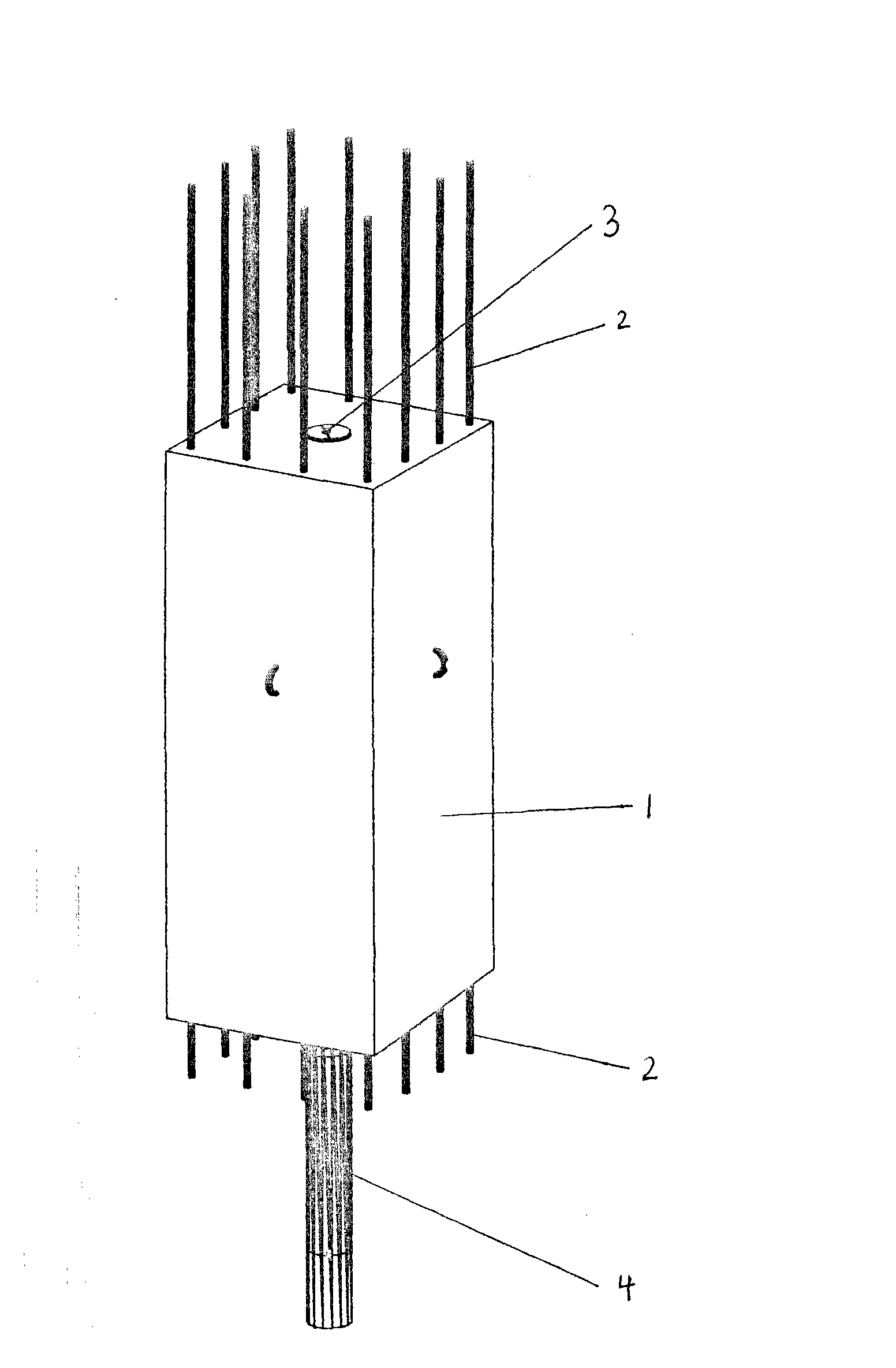
[0030] Prefabricated columns, the structure of which is as figure 1 As shown, including the column body 1 and the pre-installed steel bars, the stressed steel bars 2 protrude from the upper and lower end surfaces of the column body, and there are 4 bars on each side. The lower end surface of the column body 1 is a slope of 15°. There is movable guide reinforcing bar 5 inside, and there is guide hole 3 coaxial with column body 1 lower end face core column 4 in the center of column shaft 1 upper end surface, and active cold extruded sleeve 6 is arranged on the stressed reinforcing bar 2 upper end.

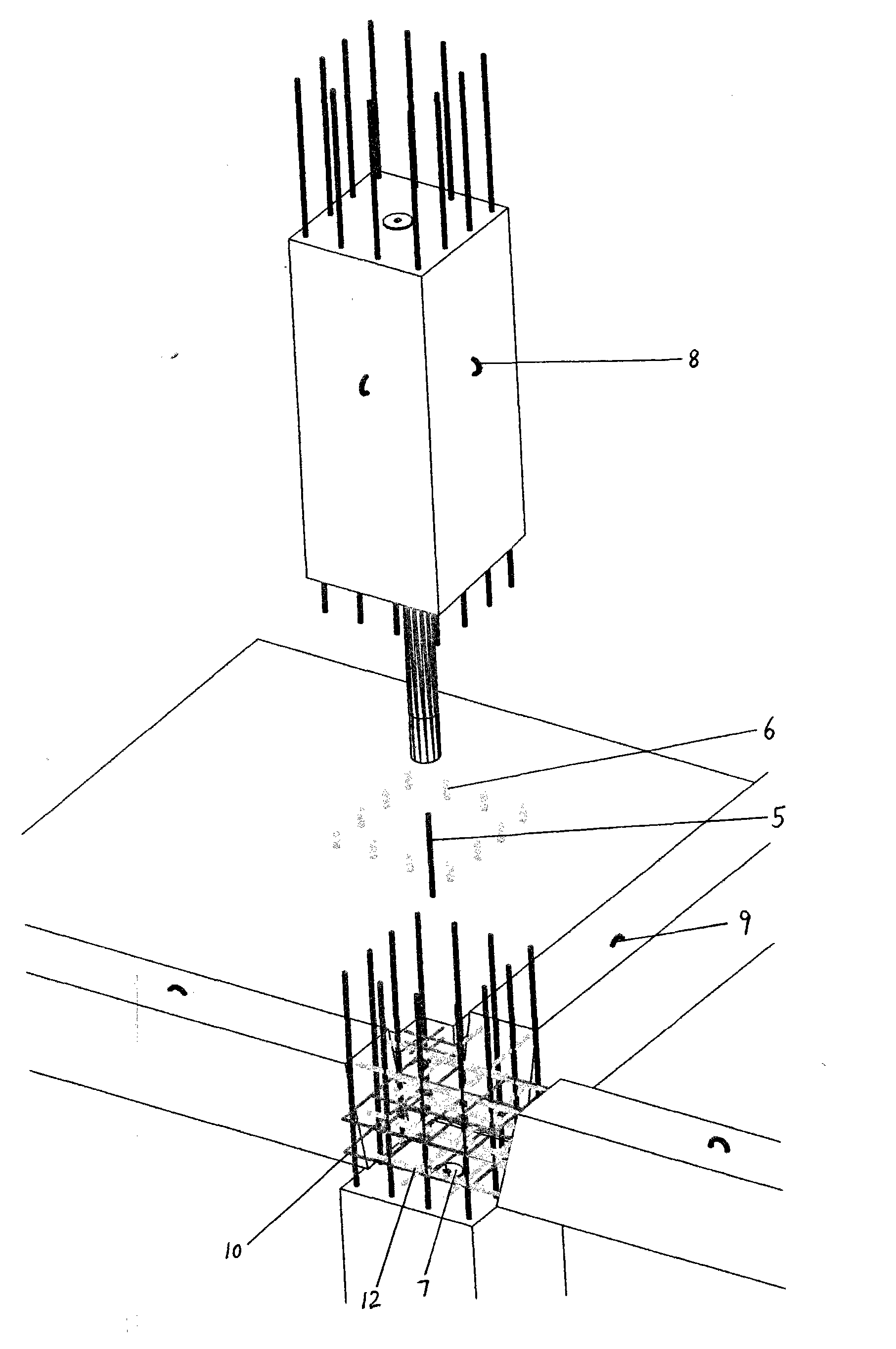
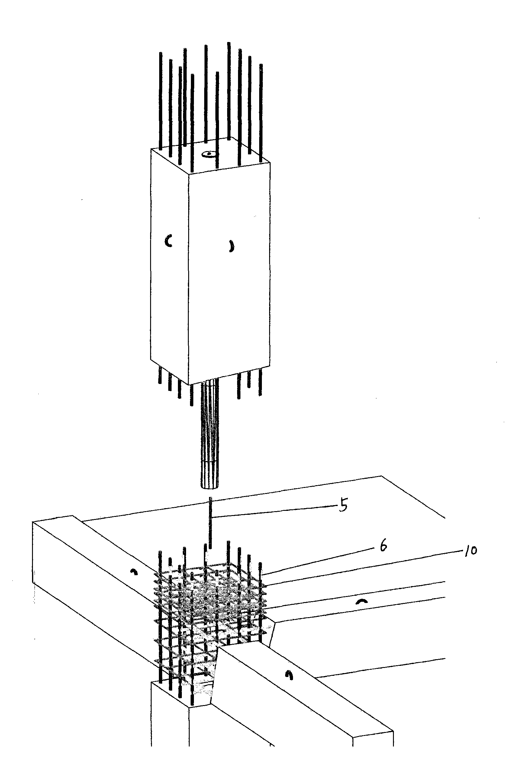
[0031] When constructing the standard layer of frame structure (such as figure 2 As shown), firstly install the prefabricated columns of the lower floor, and after the reinforcement binding or welding at the joints of the beams, slabs and columns is completed, place a number of semi-circular gaskets 7 on both sides of the guide holes of the p...

Embodiment 2

[0035] Embodiment 2 Prefabricated shear wall

[0036] Prefabricated shear walls, the structure of which is Figure 5 As shown, including the wall 1 and the pre-installed steel bars, the stressed steel bars 2 and the vertically distributed steel bars 13 protrude from the upper and lower end faces of the wall body 1, the lower end face of the wall body 1 is a slope of 15°, and there are two symmetrically distributed core columns in the middle 4. There is a guide hole 3 in the middle of the upper end of the wall 1 that is consistent with the core column 4 on the lower end of the wall 1.

[0037] When constructing the standard layer of shear wall structure (such as Figure 6 As shown), first install the prefabricated shear wall on the lower floor, and after the reinforcement binding or welding at the joints of beams, slabs and shear walls is completed, place a number of half-rings on both sides of the guide hole 3 on the upper prefabricated shear wall Gasket, the sum of its thic...


PUM


Abstract

The invention provides a prefabricated vertical member (including a pillar and a wall), which mainly comprises a member body and a prefabricated reinforcing bar (the reinforcing bar is the joint name of a principle bar longitudinally arranged along the member body, a vertically-distributed reinforcing bar, a hooping and a tie bar), and the principle bar or the principle bar and the vertically-distributed reinforcing bar stretch out of the upper end surface and the lower end surface of the member body. The prefabricated vertical member is characterized in that a core column is arranged in the middle of the lower end surface of the member body. The invention has the advantages that the installation of the prefabricated vertical member has no conflict with the anchoring of beam steel at a support, so as to meet the code requirement of the structure of cast-in-situ reinforced concrete; the core column is adopted for bearing load, the upper-layer construction operation can be carried out when in the joint concreting; no special design is needed; the connection of the reinforcing bar and the binding of a template are carried out at a floor slab, thereby not only ensuring the safety of workers, but also obviously improving the construction efficiency and the construction quality; the quantity of overhead work can be greatly decreased; the quantity of cast-in-situ concrete can be greatly decreased; and the operation is carried out at the floor slab, therefore, the construction speed is greatly improved.

Description

technical field [0001] The invention relates to building elements, prefabricated vertical elements - columns and walls. Background technique [0002] With the acceleration of China's urbanization process, the society's demand for high-rise residences is becoming increasingly urgent. Traditional buildings are constructed on site (including steel bar binding, formwork support, concrete pouring, etc.). The technical level is uneven, and the amount of high-altitude operations is large, and there are problems such as large consumption of formwork and support materials, low construction efficiency, long construction period, and difficult control of project quality. However, the existing prefabricated component construction methods and joint treatment at home and abroad can only meet the requirements of the precast concrete specification, but not the requirements of the Chinese cast-in-place reinforced concrete specification. Therefore, technical exploration is being carried out on...

Claims


Application Information

Patent Timeline
Patent Type & Authority Applications(China)
IPC IPC(8): E04B1/20E04B1/21E04B2/00E04C3/34E04B1/58E04B1/61
Inventor 管乃彦
Owner 管乃彦
Why Eureka
Try Eureka