Method for detecting hearth radiation energy signal and method for controlling boiler combustion by using same

A detection method and radiant energy technology, applied in the control of combustion, radiation pyrometry, optical radiation measurement, etc., can solve the problems of large radiant energy signal pulsation, frequent action of the mechanism, affecting the operation of the unit, etc., to achieve stable radiant energy signal, Improve control quality and more realistic effect of combustion conditions

Inactive Publication Date: 2010-07-28
HUAZHONG UNIV OF SCI & TECH
View PDF1 Cites 21 Cited by
  • Summary
  • Abstract
  • Description
  • Claims
  • Application Information

AI Technical Summary

Problems solved by technology

[0014] The invention provides a method for detecting the furnace radiant energy signal, and at the same time provides a method for using the furnace radiant energy signal to control the combustion air volume of the furnace and control the desuperheating water of the superheater, so as to solve the problem of using a single flame detector in the existing detection method The pulsation of the radiant energy signal is large. If it is introduced into the relevant control loop of the distributed control system (DCS), it will cause frequent actions of the actuator, or even disturbance and misoperation, which will seriously affect the operation of the unit.

Method used


Image

  • Method for detecting hearth radiation energy signal and method for controlling boiler combustion by using same
  • Method for detecting hearth radiation energy signal and method for controlling boiler combustion by using same
  • Method for detecting hearth radiation energy signal and method for controlling boiler combustion by using same

Examples


Embodiment Construction

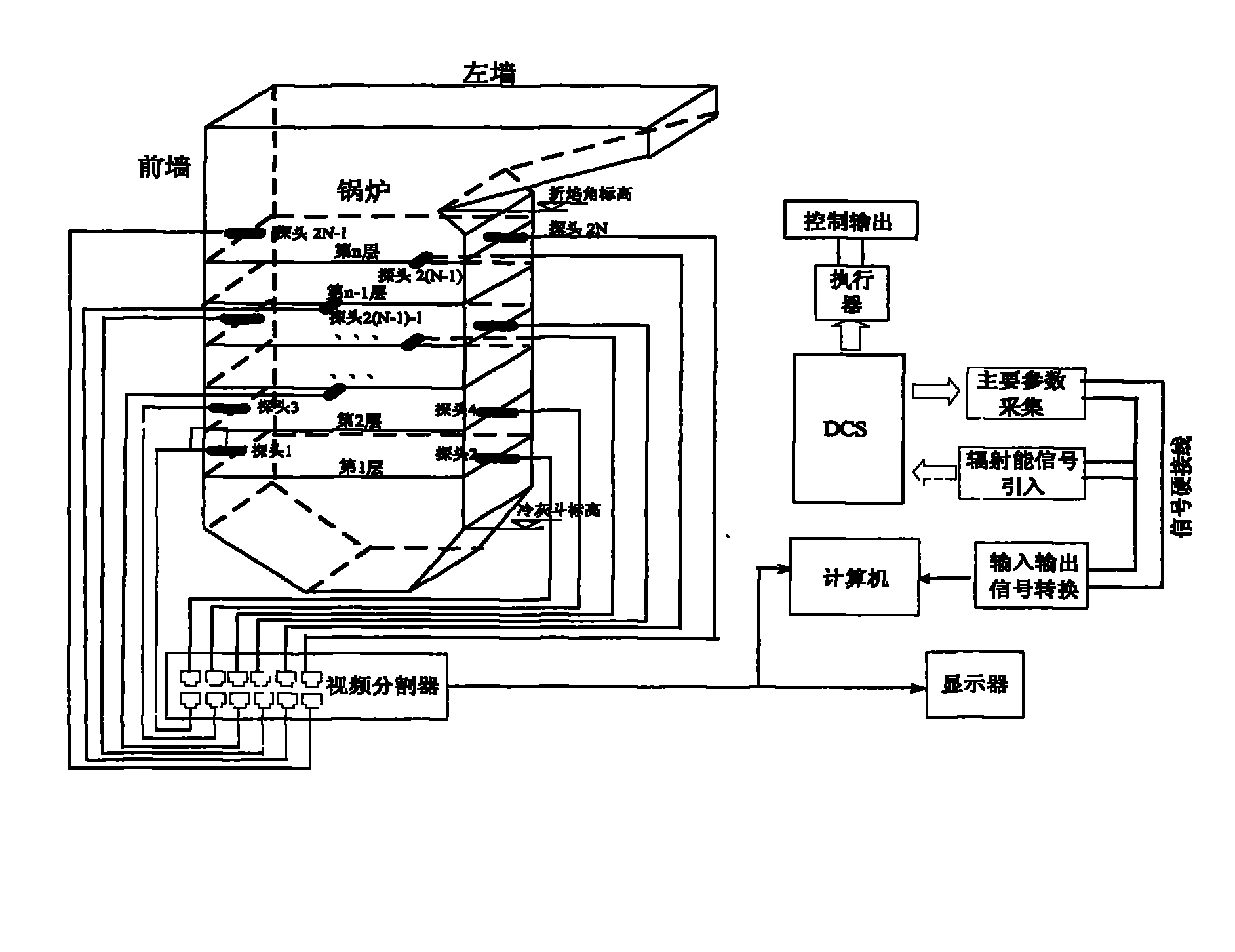
[0040] The detection and control system of the present invention has a structure such as figure 1 As shown, in the boiler furnace space, above the cold ash hopper and below the refraction angle, multiple flame probes are installed along the height, and the flame image is transmitted to the video splitter through the coaxial cable, and then synthesized into one image. Considering the real-time nature of image data processing, the image pixels of each flame probe are set to 30×30, and the synthesized video signal is led to the monitor one way for real-time flame monitoring of the entire furnace, and the other way is led to the computer to extract the furnace radiation can signal. The equipment for optimal control using radiant energy signals includes DCS system, on-site actuators, configuration software, communication lines, air volume and oxygen volume control loops, and desuperheating water control loops, all of which are existing equipment on site.

[0041] For a 300MW quadr...


PUM


Abstract

The invention provides a method for detecting a hearth radiation energy signal and a method for controlling boiler combustion by using the same, and belongs to the field of combustion monitoring and controlling. The method for detecting the hearth radiation energy signal comprises steps of analog-to-digital conversion, color value extraction and hearth radiation energy signal calculation. In the method for controlling air quantity of hearth combustion, the optimum oxygen quantity calculated by using the hearth radiation energy signal, set oxygen quantity and set offset are added, and the sum is sent to an oxygen quantity regulator to control the air quantity of the hearth combustion. The method for controlling superheater attemperating water comprises the steps of combining the hearth radiation energy signal with a heat signal to form a heat value signal; and introducing the heat value signal to a heat regulator to control the superheater attemperating water. The radiation energy signal detected by the method has the advantages of stability, reliability, capability of accurately reflecting the combustion situation in the hearth space in real time, and strong correlation with unit operation parameters; and when the new heat value signal constructed by the radiation energy signal is introduced to air supply and attemperating water control loops of the unit, the control effect of the unit can be optimized, and the efficiency of the unit can be improved. Therefore, the method for controlling the boiler combustion is suitable for combustion optimization control of a pulverized coal fired boiler of a thermal power generating unit.

Description

technical field [0001] The invention belongs to the field of combustion monitoring and control, and is suitable for the optimization control of combustion of pulverized coal combustion boilers of thermal power units. Background technique [0002] The thermal power unit is a multi-stage energy conversion system: from the fuel entering the furnace to releasing radiant energy (fast process), the radiant energy is further transferred to the boiler outlet steam (slow process) through heat conduction and convection, and the steam enters the steam turbine to drive the generator Electricity is generated (fast process), and the entire energy conversion system can be regarded as a process of energy conversion that is fast at both ends and slow in the middle. The current unit load control strategy has no effective way to overcome the influence of the slow process in the middle, which leads to the restriction of the unit's variable load operation ability and the improvement of the unit'...

Claims


Application Information

Patent Timeline
Patent Type & Authority Applications(China)
IPC IPC(8): G01J5/00F23N3/00F22G5/20
Inventor 罗自学周怀春汪飞
Owner HUAZHONG UNIV OF SCI & TECH
Why Eureka
Try Eureka