Composite fiber detection module and device

A composite optical fiber and detection module technology, which is applied in the direction of measuring devices, optical devices, fiber mechanical structures, etc., can solve the problems of difficult to achieve large range and orientation determination, poor TDR sensitivity, and small optical signal loss, etc., and achieve good monitoring effect , small transmission loss, simple operation

Inactive Publication Date: 2010-07-28
CHONGQING UNIV
View PDF0 Cites 18 Cited by
  • Summary
  • Abstract
  • Description
  • Claims
  • Application Information

AI Technical Summary

Problems solved by technology

[0004] At present, coaxial cable-based time domain reflectometry (TDR) monitoring technology, optical time domain reflectometry and Brillouin optical time domain reflectometry (BOTDR) are domestic research hotspots, but these technologies are used in slope stability monitoring. Each has its own defects. Among them, TDR has poor sensitivity when there is no shear force, so it is difficult to act on the measurement occasions with high initial

Method used


Image

  • Composite fiber detection module and device
  • Composite fiber detection module and device
  • Composite fiber detection module and device

Examples


Embodiment 1

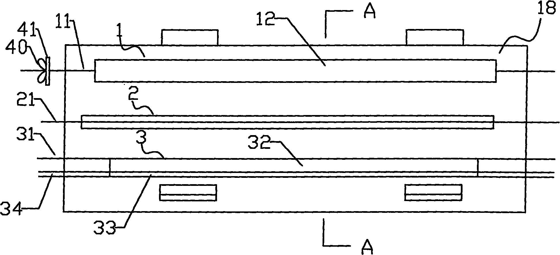
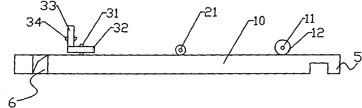
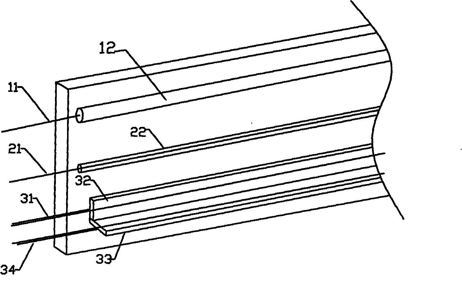
[0033] Such as Figure 1 to Figure 3 As shown, the composite optical fiber detection module of the present embodiment includes a base material 18 having a force-bearing surface, and the force-bearing surface of the base material 18 is provided with optical fiber structures I1, optical fiber structures II2 and Fiber Optic Structure III 3;

[0034] The optical fiber structure I 1 is a tubular structure, including an optical fiber I 11 and a steel pipe 12. The part of the optical fiber I 11 located on the force-bearing surface is protected by being sleeved into the steel pipe 12. The optical fiber I 11 is provided with a bow-tie structure 40, such as figure 1As shown, the bowknot structure 40 is formed behind the optical fiber 1 after passing through the baffle 41, and plays an elongated role when the optical fiber 1 is subjected to an external force. In practice, there can be more than one bowknot structure, respectively It is set at the position where both ends of the steel pi...

Embodiment 2

[0045] Such as Figure 7 As shown, the difference between the second embodiment and the first embodiment is that the strain mounting substrate II is not used, but the optical fiber III 31 is made of an optical fiber sensor engraved with a grating. The principle is to engrave a Bragg grating inside the optical fiber, Then use the fiber tuner to emit light of a certain frequency band, and reflect light of a certain wavelength after encountering the grating. In this way, when the external force changes, the distance of each grating will change, so the wavelength of the reflected light will also change. The data can realize the determination of the direction of external stress.

[0046] The composite optical fiber detection device using the composite optical fiber detection module of this embodiment includes an optical fiber tuner for emitting a light source and a spectrometer for recording light wave changes. The connection is simple and the technology is mature. Compared with th...


PUM

PropertyMeasurementUnit
Lengthaaaaaaaaaa
Outer diameteraaaaaaaaaa
The inside diameter ofaaaaaaaaaa

Abstract

The invention discloses a composite fiber detection module comprising a substrate having a stress bearing surface, wherein a fiber structure I, a fiber structure II and a fiber structure III which are parallel up and down are arranged on the stress bearing surface; the fiber structure I is of a tubular structure and used for great measuring range measurement of shear force; the fiber structure II is of a single fiber structure and used for initial high-accuracy survey of the shear force; and the fiber structure III is of an embedded type structure and used for direction judgment. Through arranging three different fiber structures on the stress bearing surface of the same substrate, the composite fiber detection module can realize the great measuring range and initiall high-accuracy survey measurement and the direction judgment and obtain accurate and comprehensive information. During actual use, a plurality of composite fiber detection modules can be mutually connected to form a three-dimensional structure or extend along the same direction plane, thereby greatly improving the flexibility of the application of the module. In addition, the invention also discloses a composite fiber detection device.

Description

technical field [0001] The invention relates to the technical field of using an optical fiber device to realize synchronous measurement of deformation and motion direction, in particular to a composite optical fiber detection module and a composite optical fiber detection device. Background technique [0002] my country is one of the countries with the most serious geological disasters in the world. Every year, hundreds of millions of losses are caused by landslides and other slope instability disasters, which seriously affect the safety of people's lives and property. Therefore, it is necessary to establish an effective monitoring network and timely forecast And protection has become an important way to resist disasters and reduce losses. [0003] Optical fiber sensing technology is to realize the measurement of environmental parameters by measuring the changes of certain parameters (such as intensity, phase, frequency, polarization state, etc.) , the optical fiber sensor us...

Claims


Application Information

Patent Timeline
IPC IPC(8): G01L1/24G01B11/16G01B11/02G02B6/44
Inventor 朱正伟刘邦袁侨英刘东燕刘京诚张倩
Owner CHONGQING UNIV
Why Eureka
Try Eureka