Method and device for isolating lights

An optical isolation and incident light technology, applied in the field of optical communication, can solve the problems of expensive crystal, high process requirements and high cost, and achieve the effect of reducing cost, improving performance and reducing packaging simplicity.

Inactive Publication Date: 2010-07-28
SUPERXON (CHENGDU) TECH LTD
View PDF0 Cites 5 Cited by
  • Summary
  • Abstract
  • Description
  • Claims
  • Application Information

AI Technical Summary

Problems solved by technology

However, crystals used as Faraday magnetic media are expensive, the cost is high, and the process requirements for packaging are relatively high.

Method used


Image

  • Method and device for isolating lights
  • Method and device for isolating lights

Examples


Embodiment Construction

[0018] The technical solutions of the present invention will be further described below in conjunction with the accompanying drawings and through specific implementation methods.
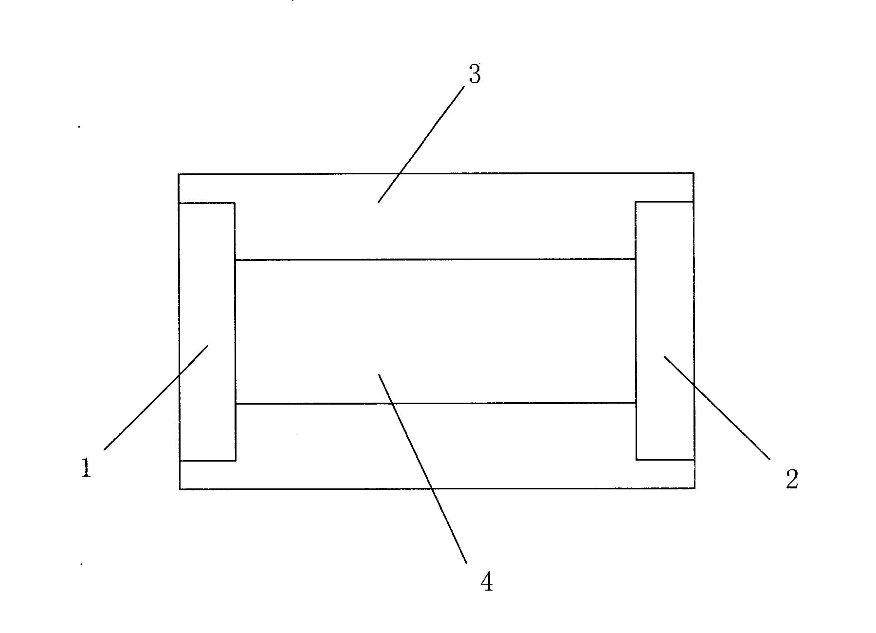
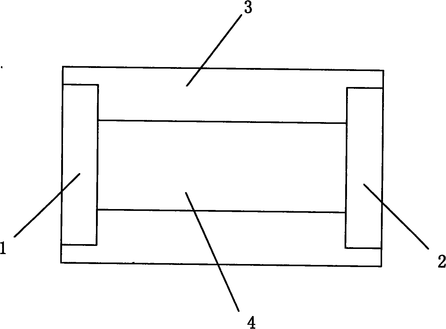
[0019] The main idea of ​​the technical solution of the present invention is based on the use of a 3 / 4 glass slide, which is an optical device that can generate an additional optical path difference or phase difference between two mutually perpendicular optical vibrations, and converts the incident optical signal into linearly polarized light , so that the amplitudes of the reflected light generated on both sides of the glass cancel each other out, forming incoherent light, enhancing the transmittance of the incident light, and finally realizing the one-way low-loss transmission of the incident light.

[0020] figure 1 It is a structural schematic diagram of the optical isolation device in the specific embodiment of the present invention. Such as figure 1 As shown, the optical isolation device inc...


PUM


Abstract

The invention discloses a method and a device for isolating lights. Incident lights penetrate through an optical filter so as to filter out lights with needless wavelengthes; the filtered incident lights rip into a 3 / 4 slide along the direction perpendicular to the 3 / 4 silde; o lights and e lights in the 3 / 4 silde have the same propagation direction and orthogonality vibration directions; and emergent lights formed by the o lights and the e lights are linearly polarized lights which are perpendicular to the slide. By utilizing the technical scheme of the invention, and under the premises of ensuring high isolation, low insertion loss, high stability, high reliability, lowered cost and simple package, the filteration effect can be achieved at the same time, so that the properties of optical products are further improved.

Description

technical field [0001] The invention relates to the technical field of optical communication, in particular to an optical isolation method and device. Background technique [0002] Semiconductor lasers and optical amplifiers are very sensitive to reflected light from connectors, splicing points, filters, etc., and lead to performance degradation. How to avoid the interference of reflected light has always been a major problem in the field of optical communications. The function of an optical isolator is to allow light to pass in one direction and block light in the opposite direction. The traditional optical isolator uses the non-reciprocity of Faraday rotation to change the propagation direction of the incident light and reflected light in the Faraday rotator, so that the polarization direction of the reverse light is orthogonal to the direction of the polarizer, completely blocking the reflection The transmission of light, so that the incident light passes through smoothl...

Claims


Application Information

Patent Timeline
Patent Type & Authority Applications(China)
IPC IPC(8): G02B27/28
Inventor 谢义芳
Owner SUPERXON (CHENGDU) TECH LTD
Why Eureka
Try Eureka