Correction method of a photomask

A photomask and light transmittance technology, applied in the field of photomask correction, can solve the problems of poor light transmittance, deterioration, insufficient light transmittance in the correction part, etc., and achieve the effect of preventing diffuse reflection

Inactive Publication Date: 2010-07-28
HOYA CORP
View PDF1 Cites 4 Cited by
  • Summary
  • Abstract
  • Description
  • Claims
  • Application Information

AI Technical Summary

Problems solved by technology

However, in the method disclosed in Patent Document 1, since a transparent resin is used, there is a problem that the light transmittance of the corrected part is insufficient, and it is opaque to the transfer wavelength.
In particul

Method used


Image

  • Correction method of a photomask
  • Correction method of a photomask
  • Correction method of a photomask

Examples


no. 1 approach

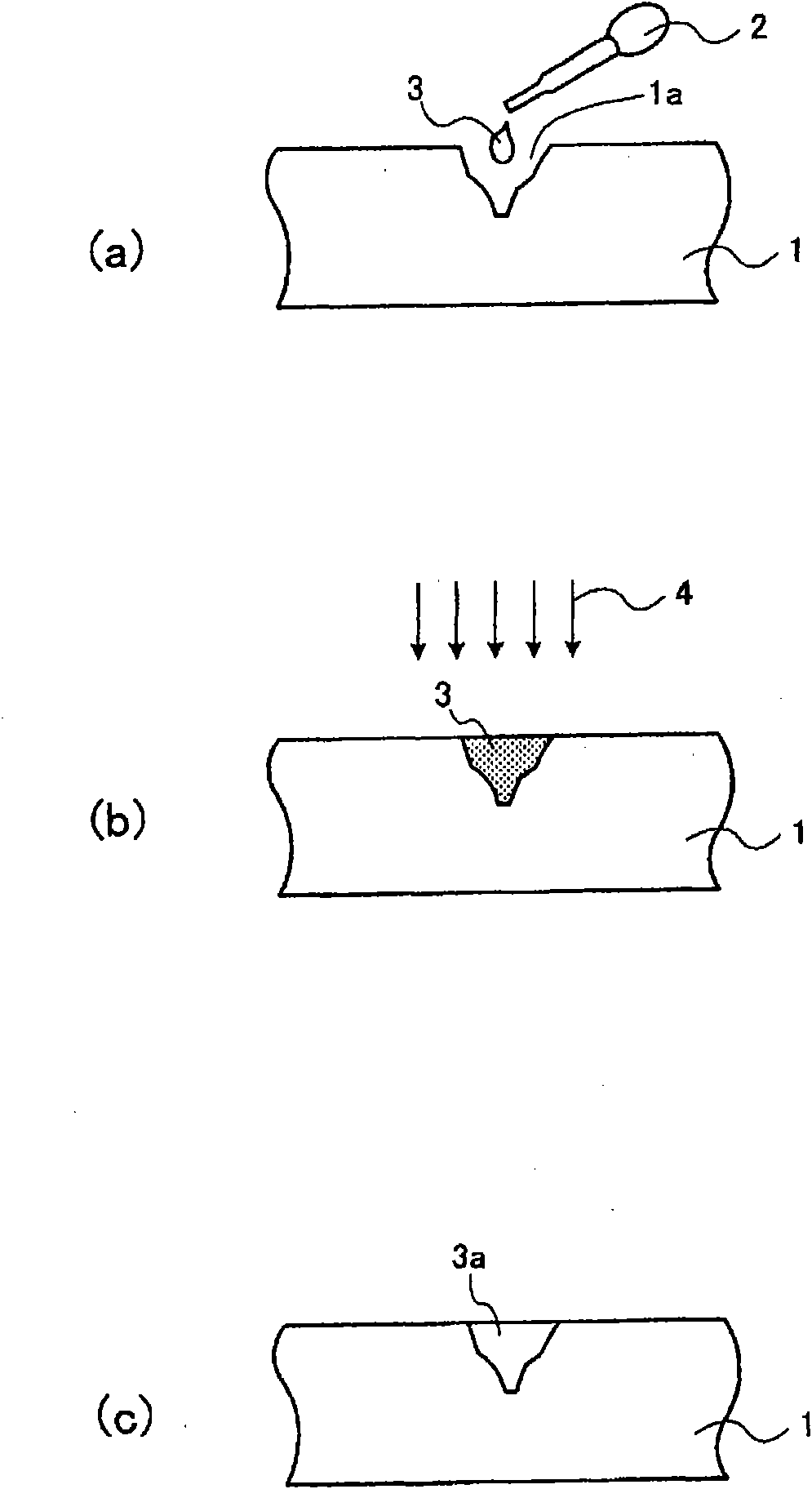
[0025] In this embodiment, a case where liquid glass is directly applied and hardened on the damage existing on the back surface of the photomask will be described.

[0026] The photomask of the present invention includes a photomask for LSI (Large Scale Integration), a photomask for FPD (Flat Panel Display), and a photomask for PWB (Printed Wiring Board: printed wiring board). Any kind of mask in photomask. Moreover, as a photomask in this invention, a binary mask (Binary Mask), a halftone mask (HalfTone Mask), an extreme ultraviolet mask (EUV Mask), etc. are mentioned. The photomask according to the present invention is particularly effective for a mask for FPD having a rectangular shape of 300 mm or more in one side and weighing 150 g or more. The above-mentioned photomask may be a multi-tone photomask including a transfer pattern having at least a light-shielding portion and a light-transmitting portion, and further having a semi-transmitting portion through which a part ...

no. 2 approach

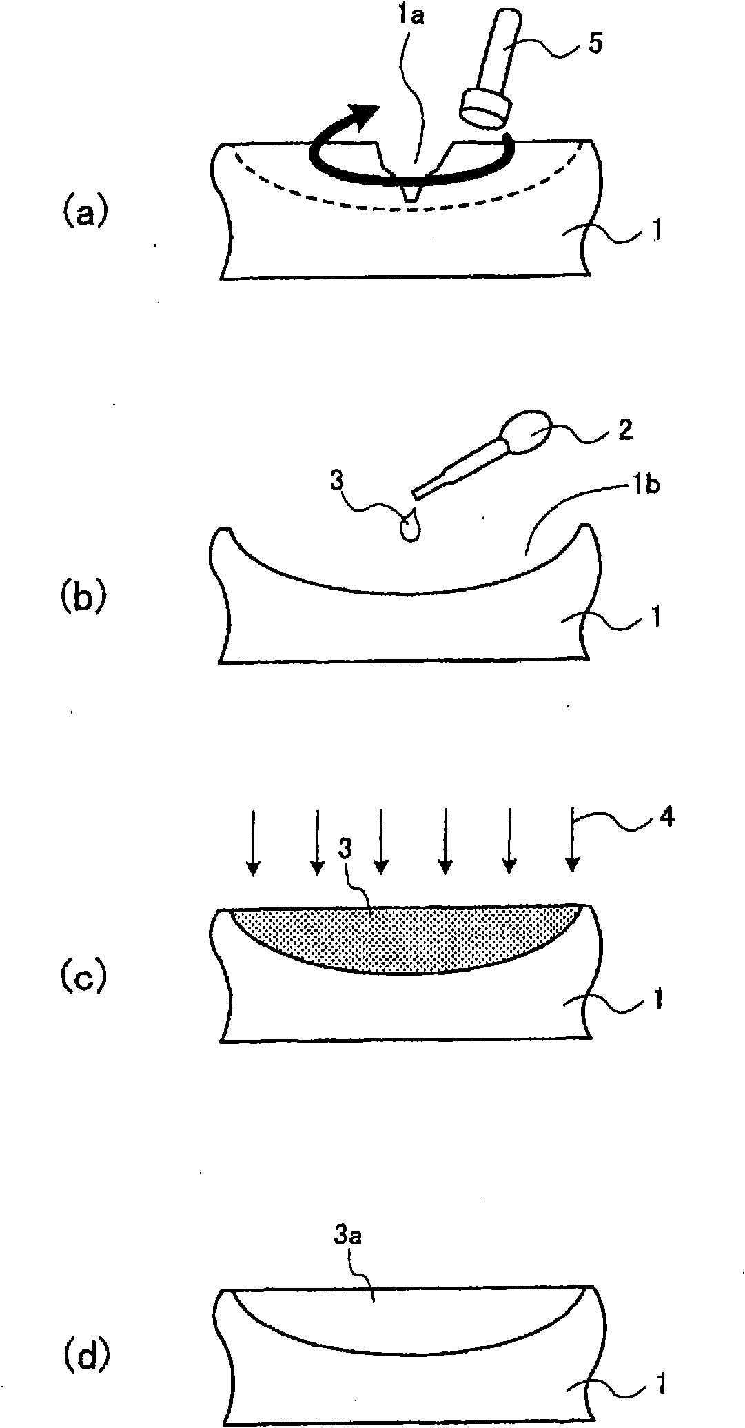
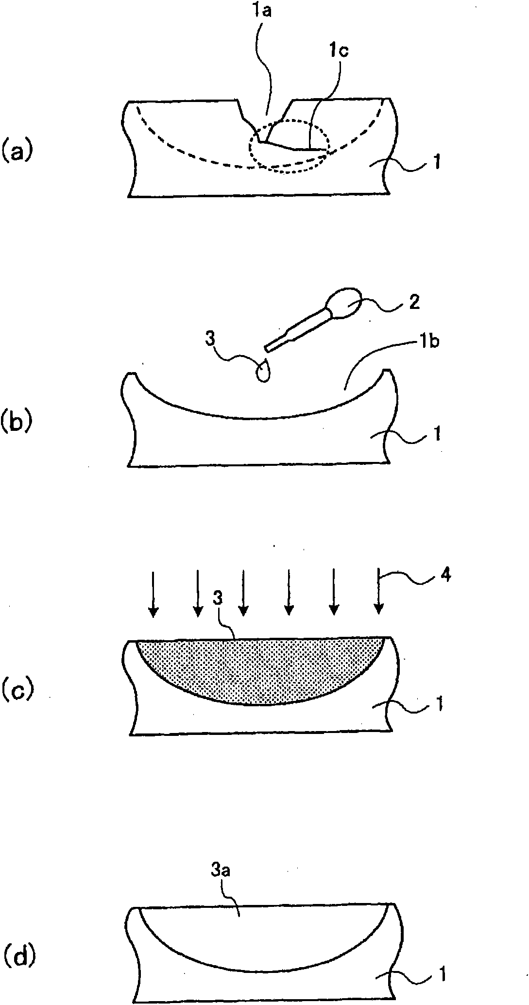
[0042] In this second embodiment, a case will be described where liquid glass is applied to the damaged region after removing the damaged region on the back surface of the photomask and then cured.

[0043] figure 2 (a)~(d) and image 3 (a)-(d) is a figure for demonstrating the correction method of the photomask which concerns on 2nd Embodiment of this invention. Here, the case where liquid glass is cured by ultraviolet rays will be described.

[0044] exist figure 2 In the shown mode, on the backside of the photomask 1 ( figure 2 The surface on the upper middle side) has damage 1a. Such as figure 2 As shown in (a), the router 5 is used to grind the region including the damage 1a (the region enclosed by the dotted line). Thus, if figure 2 As shown in (b), the recessed part 1b is formed in the back surface of the photomask 1. Next, the liquid glass 3 is applied to the concave portion 1b. Here, if figure 2 As shown in (b), the liquid glass 3 is applied by droppin...


PUM


Abstract

Th invention provides a correction method of a photomask, comprising a coating a liquid glass on the damage present on the back of the photomask, wherein the liquid glass is hardened to form a glass with more 70% transmittance and more 1.4 reflection index; hardening the liquid glass.

Description

technical field [0001] The present invention relates to a method of modifying a photomask used in a photolithography process. Background technique [0002] The photomask is used in a photolithography process in a manufacturing process of a liquid crystal display device or the like. The above photomask is composed of, for example, a transparent substrate and a light-shielding film pattern (mask pattern) formed on the transparent substrate. When there is damage on the back surface of the photomask, the exposure light is diffusely reflected at the damaged part during exposure, and the desired transfer cannot be performed. In particular, the liquid crystal panels that have recently begun to appear are rectangular with a single side of more than 1000 mm, and the size of the tenth-generation liquid crystal panels that will appear in the future is 2850 mm × 3050 mm, etc. If it is formed into a rectangle with a dimension of 1200mm or more on one side, the weight will also increase...

Claims


Application Information

Patent Timeline
IPC IPC(8): G03F1/00G03F1/60G03F1/72
CPCA63G11/00
Inventor 河守将典佐野道明
Owner HOYA CORP
Why Eureka
Try Eureka