Cold bending thin-wall steel beam column node

A technology of cold-formed thin-walled steel and beam-column joints, which is applied in the direction of buildings and building structures, can solve the problems of reducing joint stiffness and plastic deformation capacity, reducing structural ultimate bearing capacity, and reducing column and plate ductility, etc., and achieves seismic resistance. Superior performance, improved ultimate bearing capacity and improved ductility

Inactive Publication Date: 2010-08-04
SOUTHWEAT UNIV OF SCI & TECH
View PDF8 Cites 9 Cited by
  • Summary
  • Abstract
  • Description
  • Claims
  • Application Information

AI Technical Summary

Problems solved by technology

[0005] It is connected by welding, the airtightness is good, and the net cross-sectional area of ​​the plate will not be reduced, so it is more beneficial to use the welding method, but the repeated welding of the joints of the column will lead to a decrease in the ductility of the column and plate, or even burn through. Increase the stiffness and plastic deformation capacity of the joints, induce brittle failure of the joints, and reduce the ultimate bearing capacity of the structure as much as possible

Method used


Image

  • Cold bending thin-wall steel beam column node
  • Cold bending thin-wall steel beam column node
  • Cold bending thin-wall steel beam column node

Examples


Embodiment 1

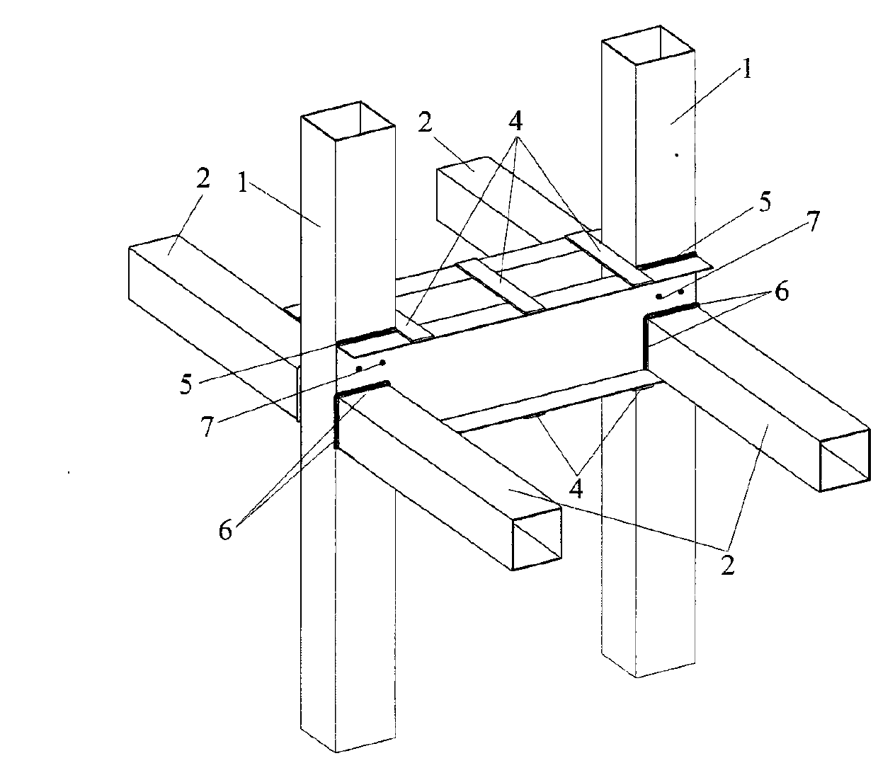
[0023] Embodiment 1 (see figure 1 ): The present invention is a kind of cold-formed thin-walled steel center column node related to structural engineering. It consists of square steel pipe columns 1, square steel pipe beams 2, C-shaped steel beams 3, trim plates 4, fillet welds 5 and 6, and self-tapping screws 7. Two square steel pipe columns 1 connect two C-shaped steel beams 3 on both sides through eight fillet welds 5; six panels 4 are welded on the upper and lower flange surfaces of the C-shaped steel beam 3, and are distributed on the C-shaped steel beam 3 mid-span and both ends; four square steel pipe girders 2 and C-shaped steel girder 3 are welded to the lower flange of C-shaped steel girder 3 through fillet welds 6 (when the web height of C-shaped steel girder 3 exceeds the specification requirements, the The self-tapping screw 7 connects the square steel pipe column 1 with the transverse C-shaped steel beam 3). In this type of node, the C-shaped steel beam 3 is arr...

Embodiment 2

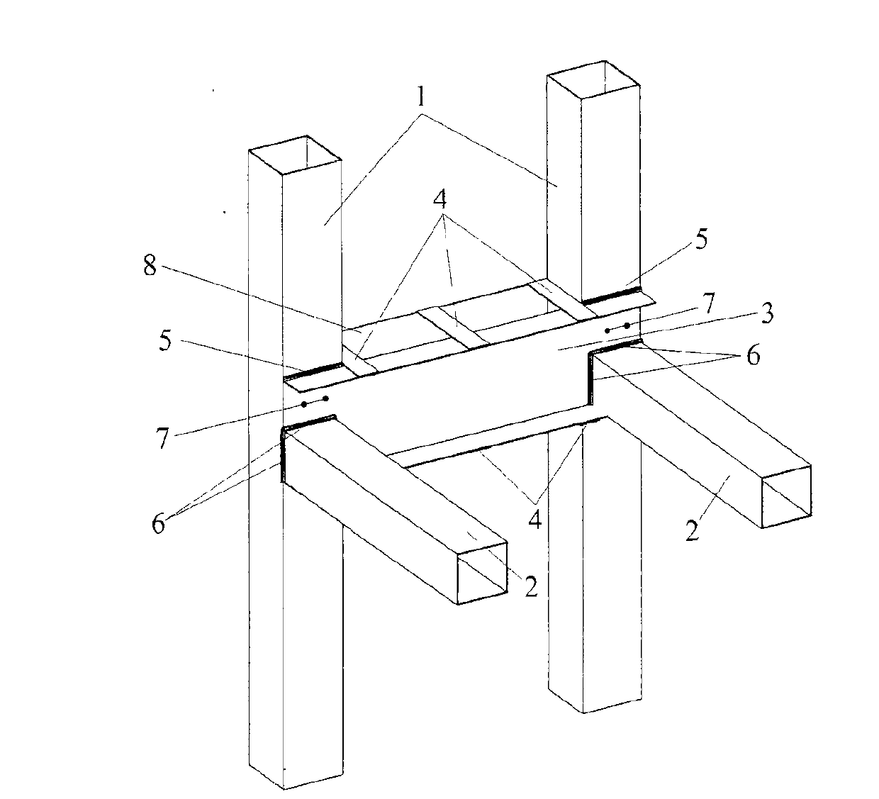
[0024] Embodiment 2 (see figure 2 , image 3 ): The present invention is a kind of cold-formed thin-walled steel side column node related to structural engineering. It consists of square steel pipe columns 1, square steel pipe beams 2, C-shaped steel beams 3, steel plates 8, trim plates 4, fillet welds 5, fillet welds 6, and self-tapping screws 7. Two square steel pipe columns 1 and a C-shaped steel beam 3 are welded on one side through four fillet welds 5, and two square steel pipe columns 1 and a steel plate 8 are welded on the other side through four fillet welds 5; the C-shaped steel beam 3 and the upper and lower surfaces of the steel plate 8 are welded with six panels 4, evenly distributed between the square steel pipe columns 1; two square steel pipe beams 2 are welded to the lower flange of the C-shaped steel beam 3 through the fillet weld 6 (when the steel plate When the height of the web plate of the C-shaped steel beam 3 exceeds the specification requirement, sel...

Embodiment 3

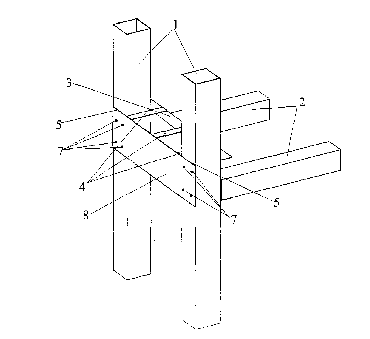
[0025] Embodiment 3 (see Figure 4 , Figure 5 ): The present invention is a kind of cold-formed thin-walled steel corner column joint related to structural engineering. It consists of square steel pipe columns 1, square steel pipe beams 2, C-shaped steel beams 3, steel plates 8, trim plates 4, fillet welds 5, fillet welds 6, and self-tapping screws 7. A square steel pipe column 1 and a C-shaped steel beam 3 are welded on one side through a fillet weld 5, and a square steel pipe column 1 and a steel plate 8 are welded on the other side through a fillet weld 5; the C-shaped steel beam 3 and the steel plate 8 The upper and lower surfaces are welded with panel 4, and the C-shaped steel beam 3 and the square steel pipe girder 2 are welded to the lower flange of the C-shaped steel beam 3 through the fillet weld 6 (when the height of the web of the steel plate 8 and the C-shaped steel beam 3 exceeds the specification requirements , can adopt self-tapping screw 7 to connect it with...


PUM


Abstract

The invention discloses a cold bending thin-wall steel beam column node, which comprises a square steel tubular column (1), a square steel tubular beam (2) and a C-shaped steel beam (3). The steel beam column node is characterized in that the C-shaped steel beam (3) is welded on the square steel tubular column (1), and the square steel tubular beam (2) is welded on the C-shaped steel beam (3). The C-shaped steel beam (3) and the square steel tubular column (1) can be connected by self-tapping screws (7). The cold bending thin-wall steel beam column node overcomes the defect of the conventional cold bending thin-wall steel beam column node connection; and the node has the advantages of definite stress transfer pathway, predominant earthquake resistance and simple and feasible construction operation, can be widely applied to connection of sections of various cold bending thin-wall steel rods, and is particularly suitable for a structural system adopting a plug-in retaining wall.

Description

technical field [0001] The invention relates to a steel structure node, in particular to a cold-formed thin-walled steel beam-column node. Background technique [0002] Because the cold-formed thin-walled steel structure house has light weight of the rods, no large-scale construction machinery is required during construction, it is easy to operate, has good seismic performance, energy saving, land saving, material saving, and environmental protection, which is conducive to the industrialization of house construction and has a construction cycle. A series of advantages such as short length and good comprehensive benefits are very suitable for use in house construction. At present, this system has become an important form of low-rise residential buildings in developed countries such as the United States, Japan, and Australia. Since the cold-formed thin-walled steel residential structure has obvious advantages in function and economy compared with other structures, China has a...

Claims


Application Information

Patent Timeline
Patent Type & Authority Applications(China)
IPC IPC(8): E04B1/58E04B1/24
Inventor 姚勇褚云朋周俐俐王汝恒雷劲松张兆强陈晓强徐斌高玉波肖术连
Owner SOUTHWEAT UNIV OF SCI & TECH
Why Eureka
Try Eureka